Installation
30 3A2098H
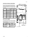
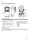
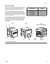
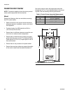
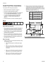
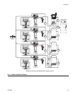
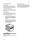
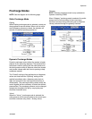
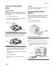
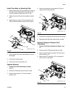
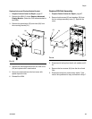
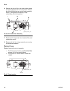
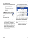
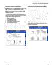
Install Gateway Module Interface
NOTE: Systems with swirl dispensers will have two gateway modules in the control center. The gateway module on
the left is the swirl control DGM module, and does not need any setup or modification. The gateway module on the
right is the automation Gateway module. This section covers the automation Gateway module.
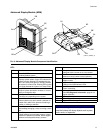
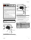
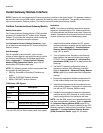
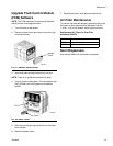
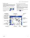
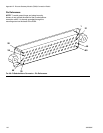
Fieldbus Communications Gateway Module
Module Description
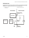
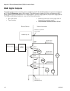
The Communications Gateway Module (CGM) provides
a control link between the PCF system and a selected
fieldbus. This provides the means for remote monitoring
and control by external automation systems.
See Automation Control (Normal Operation), page
45, for details on controlling the PCF system through the
Gateway module.
Data Exchange
Data is available by block transfer, cyclic transfer,
change of state triggered, and explicit access to individ-
ual attributes as defined by the fieldbus specification.
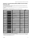
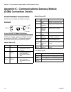
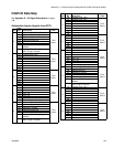
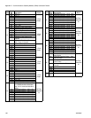
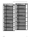
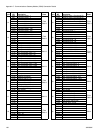
Refer to Appendix C - Communications Gateway
Module (CGM) Connection Details, page 138, for
details about PCF/fieldbus data map.
NOTE: The following system network configuration files
are available at www.graco.com
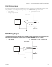
• EDS file: DeviceNet or EtherNet/IP fieldbus net-
works
• GSD file: PROFIBUS fieldbus networks
• SDML: PROFINET fieldbus networks
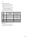
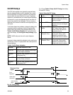
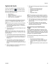
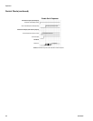
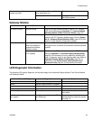
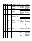
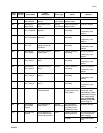
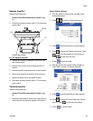
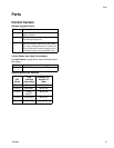
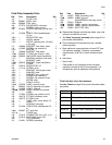
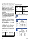
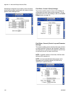
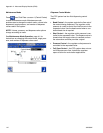
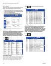
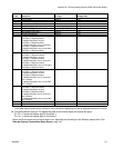
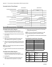
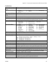
CGM Status LED Signals
*The red LED (CF) will flash a code, pause, then repeat.
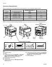
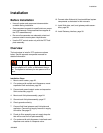
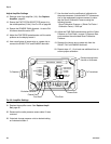
Installation
NOTE: The following installation instructions assume
the person implementing the PCF fieldbus connection
fully comprehends the fieldbus being used. Ensure the
installer understands the automation controller commu-
nication architecture and the fieldbus being used.
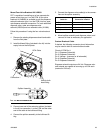
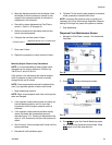
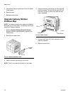
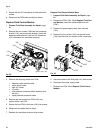
1. Install interface cables between the PCF system
and the automation controller per the fieldbus stan-
dards. Refer to Appendix C - Communications
Gateway Module (CGM) Connection Details,
page 122, for details.
2. Turn on system power. Navigate to the Gateway
setup screens and ensure the data map name is:
PCF 4FP. Refer to Appendix A - Advanced Dis-
play Module (ADM), page 99, for details about the
data map.
3. Set the PCF Gateway configuration values as
required to interface with automation controller.
Refer to Appendix A - Advanced Display Module
(ADM), page 99, for details about the configuration
settings.
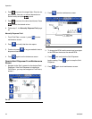
4. Retrieve the appropriate fieldbus configuration file
for the fieldbus being used from www.graco.com.
5. Install the configuration file on the automation con-
troller (fieldbus master). Configure it for communica-
tion with the PCF Gateway (fieldbus slave).
6. Establish communication between the automation
controller and the PCF Gateway to confirm the suc-
cessful configuration of the hardware and data.
NOTE: Use the ADM screens for troubleshooting field-
bus data communication problems. Refer to Appendix
A - Advanced Display Module (ADM), page 99, for
details. Also, use the LED status indicators on the PCF
Gateway module for fieldbus status information. Refer to
Appendix C - Communications Gateway Module
(CGM) Connection Details, page 122, for details.
Signal Description
Green on System is powered up
Yellow Internal communication in progress
Red
Solid
CGM hardware failure
*Red
(7 flashes)
Data map load failure
Incorrect data map for fieldbus type
No data map loaded