


Installation
26 3A2098H
Install Command Cable Kit 24B694
Follow this procedure if using the command cable kit.
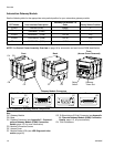
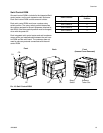
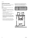
1. Install bulkhead fitting (included in the kit) into the
empty hole on the fluid plate. See F
IG
. 16 on
page 25.
2. Connect one end of the extension cable (included in
the kit) to connection 5 on the FCM and the other
end of the cable to the bulkhead fitting.
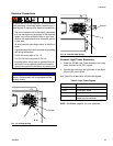
3. Connect command cable to bulkhead fitting and
wire to automation controller per the following pinout
table.
NOTE: Command cable inputs are not isolated from
PCF 24 Vdc power.
* To turn on the dispense trigger, connect the dis-
pense trigger pin to the dispense trigger ground pin
(pin 5).
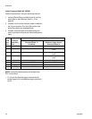
FCM
Port
Pin #
Command
Cable Wire
Color
Function
Dispense Trigger Source:
‘Command Cable’ or
‘Combined’
Dispense Trigger Source:
‘Command Cable 3x’
1 White Command voltage (0-10 Vdc) Command voltage (0-10 Vdc)
2 Brown No connection Valve 3 dispense trigger (*sourcing
input)
3 Green Dispense trigger (*sourcing input) Valve 1 dispense trigger (*sourcing
input)
4 Yellow No connection Valve 2 dispense trigger (*sourcing
input)
5 Gray Dispense trigger ground Dispense trigger ground
6 Pink No connection No connection
7 Blue Command signal ground Command signal ground
8 Red No connection No connection