Appendix A - Advanced Display Module (ADM)
3A2098H 113
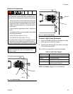
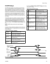
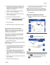
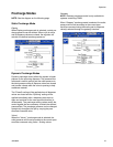
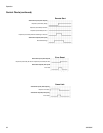
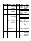
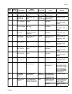
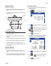
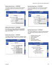
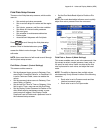
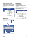
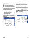
Fluid Plate x, Screen 2 (Control Center)
NOTE: Users must be out of maintenance mode in Fluid
Plate x, screen 1 in order to scroll to this screen.
NOTE: The term “Robot” on this screen refers to the
automation controller.
This screen enables users to view and monitor the cur-
rent status of the “robot” outputs and inputs. An X is dis-
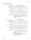
played in the applicable check box when:
• Using a style strobe
• The dispense is complete
• A dispense trigger occurs
• The dispenser (fluid plate) is ready
• The dispense is in process
• There are no alarms or errors
• The dispense volume is correct
This screen also displays the current dispense style,
command voltage, Gateway error number/code, and the
volume dispensed.
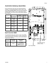
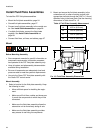
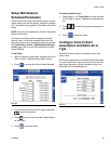
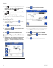
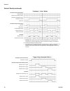
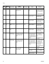
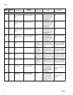
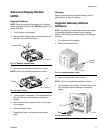
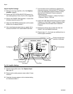
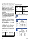
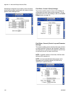
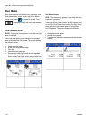
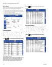
Fluid Plate x, Screen 3 (Maintenance Totalizers)
This screen enables users to view the maintenance
totalizers for each system component and the limits set
that will trigger a maintenance advisory.
Maintenance totalizers keep track of the total volume (or
hours) that each system component has been running.
If the totalizer value exceeds the set limit, the totalizer
value will turn red and a maintenance advisory is issued.
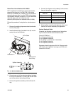
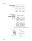
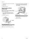
The limits are set in the Fluid Plate x, Screen 7 (Main-
tenance Advisory Limits), page 108, for the air supply,
voltage to pressure (V/P) transducer, fluid regulator,
flow meter, and all four valves.
NOTE: If a flow meter is not included in the system, this
screen shows hours instead of volume and the flow
meter entry is grayed out.