


Repair
86 3A2098H
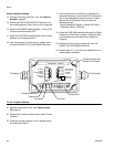
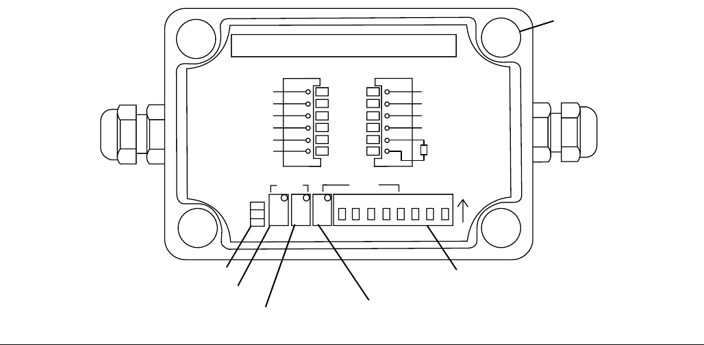
Adjust Amplifier Settings
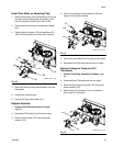
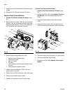
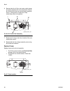
12. Remove cover from amplifier (116). See Replace
Amplifier, page 85.
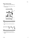
13. Ensure the EXCITATION SELECTOR jumper is in
the middle position (5 Vdc). See F
IG
. 59 on page 86.
14. Ensure the COARSE GAIN dipswitch 1 is set to ON.
All others should be set to OFF.
15. Adjust the FINE ZERO potentiometer until the outlet
pressure on the display reads 0.
16. Use a small piece of jumper wire or a paper clip to
connect the SHUNT CAL and ENABLE terminals.
17. Use the data from the certificate of calibration for
the pressure sensor (included with PCF documenta-
tion or the replacement pressure sensor) to calcu-
late the Shunt Calibration Pressure using the
following formula:
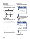
18. Adjust the FINE GAIN potentiometer until the Outlet
Pressure on Fluid Plate x, screen 5 (Pressure Sen-
sors) matches the calculated Shunt Calibration
Pressure.
19. Remove the jumper wire or paper clip from the
SHUNT CAL and ENABLE terminals.
20. Repeat steps 15 - 19 at least one additional time to
ensure proper calibration.
21. Replace the amplifier cover. See Replace Ampli-
fier, page 85.
22. Reconnect the outlet pressure sensor cable if it was
removed.
23. If desired, change pressure units to desired setting
on Advanced screen 2.
Shunt Calibration Pressure = (Shunt Cal Factor /
Calibration Factor) * 5000 psi
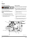
F
IG
. 59: Amplifier Settings
1
2
3
4
5
6
A
B
C
D
E
F
EXCITATION MODULE
TRANSDUCERPOWER
(+)SUPPLY
(+)SIGNAL
(-)SIGNAL
(+)EXCITATION
(-)EXCITATION
(-)OUTPUT
(+)OUTPUT
SHUNT CAL
SHUNT CAL
RESISTOR
ENABLE
EX SEL
10 VDC
5 VDC
3 VDC
ZERO
COARSE
FINE
FINE
SPAN
COARSE
12345678
ON
SUPPLY RETURN
Excitation Selector
Coarse Zero
Fine Zero
Fine Gain
Coarse Gain
Panel mounting holes.
Use #6 or #8 screws.
To Transducer
To Readout