


Installation
3A2098H 31
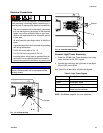
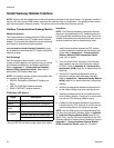
Discrete Gateway Module
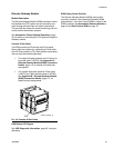
Module Description
The Discrete Gateway Module (DGM) provides a control
link between the PCF system and an automation con-
troller through discrete input and output connections.
This provides the means for remote monitoring and con-
trol by external automation systems.
See Automation Control (Normal Operation), page
45, for details on controlling the PCF system through the
Gateway module.
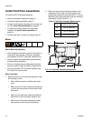
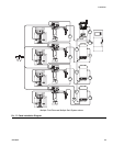
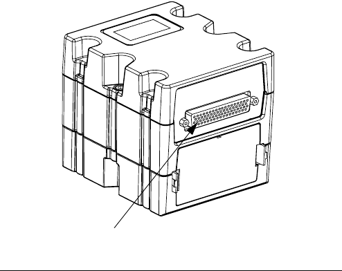
Connect D-Sub Cable
The DGM provides all I/O through the D-Sub cable.
Graco offers two options for connecting a D-Sub cable
to the D-Sub connector (CG). Both options are accesso-
ries and must be ordered separately.
•
For single fluid plate systems only:
D-Sub to fly-
ing leads cable (123793). See Appendix B -
Discrete Gateway Module (DGM) Connection
Details, page 115, for details and cable inter-
face signals.
•
For multiple fluid plate systems:
D-Sub cable
(123972) and 78-pin breakout board (123783).
See Appendix B - Discrete Gateway Module
(DGM) Connection Details, page 115, for
details and pin assignments.
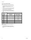
DGM Status LED Signals
See LED Diagnostic Information, page 65, for signal
definitions.
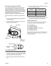
DGM Rotary Switch Position
The Discrete Gateway Module (DGM) rotary switch
must be in position 0 for Automation Gateway DGMs
and positions 1-4 for Swirl Control DGMs in order for the
DGM to operate. See Automation Gateway Module on
page 18 and Swirl Control DGM on page 19.
F
IG
. 18: Connect D-Sub Cable
r_24B681_2B9904_2b
CG