Operation
42 3A2098H
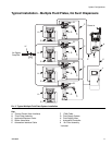
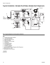
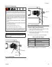
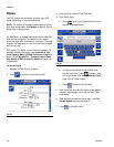
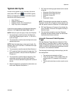
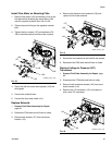
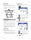
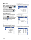
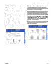
Dispense from Each Valve
Dispense from each valve that will be used in normal
operation to confirm that the entire system is installed
correctly and is capable of delivering desired results.
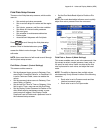
Follow the steps outlined in Dispense From Mainte-
nance Screen, page 43, to perform each of the follow-
ing applicable system verification checks.
NOTE: Each fluid plate controls only the dispense
valves connected to it.
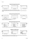
• For each valve that will be used during normal oper-
ation, dispense at each pressure or flow rate that
will be used during normal operation. This verifica-
tion check confirms that the system is capable of
delivering material at your maximum desired operat-
ing point.
• For systems that will operate multiple valves in pres-
sure mode at the same time, dispense from each
valve at the same time. This verification check con-
firms that the system is capable of delivering mate-
rial at your maximum desired operating point.
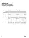
• For each valve operating in bead mode, perform an
initial teaching process. Follow this procedure after
significant system and/or material characteristic
changes.
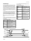
a. For each flow rate that will be used during nor-
mal operation, press until PCF achieves
the flow rate setpoint.
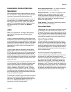
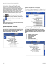
NOTE: During the initial system operation verification, it
may take four to five seconds for the system to learn
system characteristics.
b. Continue to press for several seconds
after the desire flow rate is reached to confirm
that the system is capable of maintaining the
desired flow rate.
c. Repeat Steps a and b for a range of flow rates
to confirm that the system responds quickly to
achieve setpoint when is pressed.
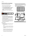
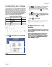
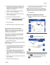
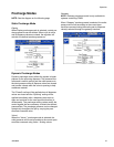
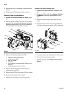
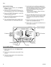
Verify Flow Meter Calibration
Most sealant and adhesive materials are compressible.
Since the flow meter measures the material under high
pressure, the actual volume of material dispensed may
vary slightly from the measured volume, due to this
compressibility. If the K-factor is not correct, the dis-
played volume will not be accurate.
Follow either of the following methods to calibrate the
flow meter during initial setup and on a routine basis to
check for flow meter wear.
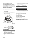
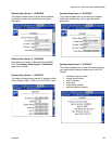
Method 1. Using a gram scale
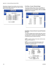
1. Record the flow meter k-factor shown on Fluid Plate
x, screen 4 (Flowmeter Settings). See F
IG
. 23 on
page 35.
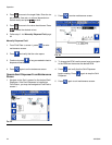
2. Use a 500 cc or larger beaker. Measure the mass of
the empty beaker.
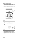
3. Manually dispense material into the beaker. Hold
the beaker so that the stream of material is sub-
merged in the captured material to minimize air
entrapment in the container.
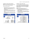
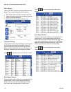
4. Record the volume dispensed on Fluid Plate x,
screen 1. See F
IG
. 30 on page 43.
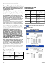
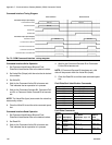
5. Calculate the actual volume dispensed:
6. Calculate the new flow meter K-factor:
7. Enter new K-factor.
8. Repeat the procedure to verify the new K-factor.
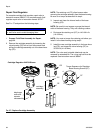
Method 2. Without using a gram scale, visual measure-
ment
1. Record the flow meter k-factor shown on Fluid
Plate x, screen 4 (Flowmeter Settings). See F
IG
. 23
on page 35.
2. Use a 500 cc or larger beaker.
fluid mass (g)
density (g/cc)
=
measure volume (cc)
K-Factor (new) =
displayed volume (cc) x K-Factor (old)
measured volume (cc)