


Operation
54 3A2098H
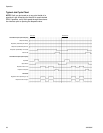
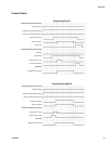
Control Charts (continued)
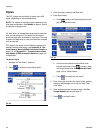
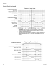
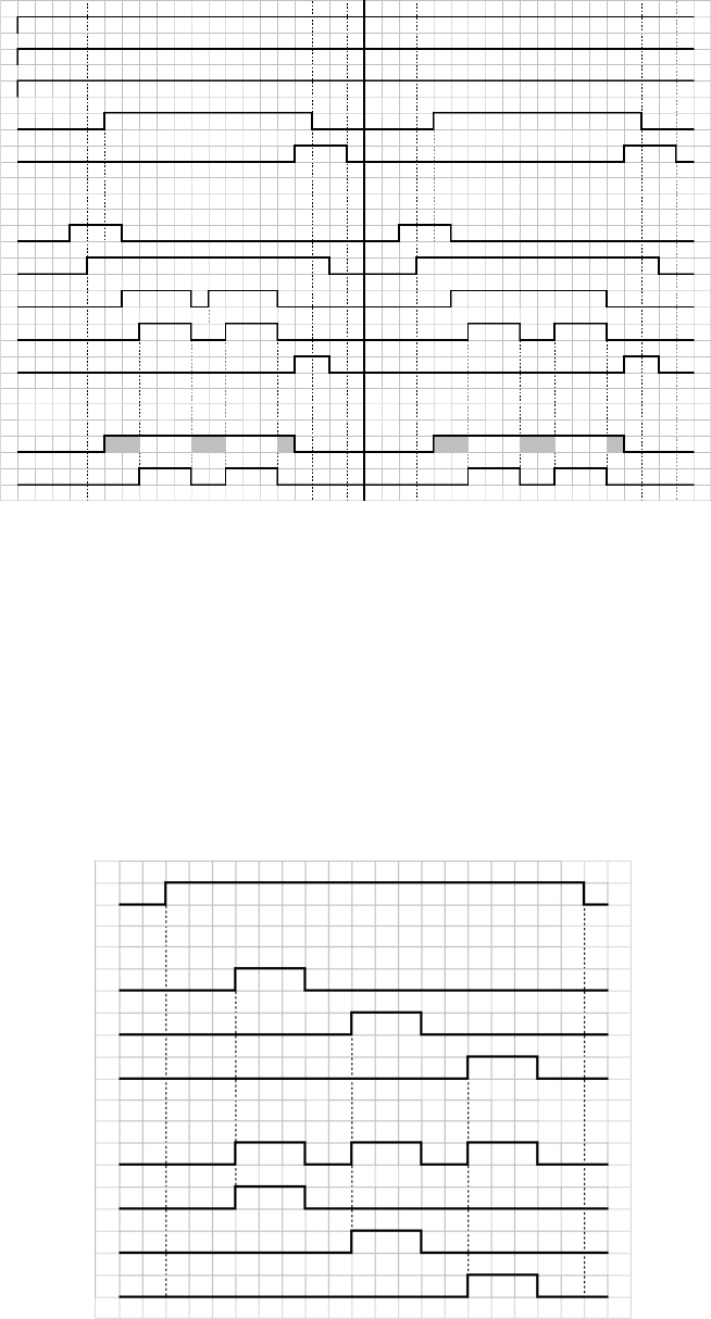
Precharge* - Valve 1 Mode
◆
* Precharge: After starting a job and prior to opening the dispense valve, the fluid pressure is
increased to try to match the dispensing pressure. This helps the consistency of the dispense.
◆
Shaded areas indicate the precharge is active.
†
Only applies to command signals when either “Command Cable” or “gateway” is selected as “Com-
mand Value Source”. In systems containing an automation gateway DGM, when “Digital” is
selected as the “Command Value Type”, the “Digital CMD 1” and “Digital CMD 2” inputs set the
command.
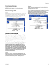
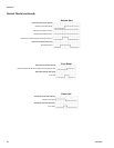
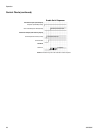
Automation Inputs (PCF Outputs)
Dispense Ready
Dispenser (Fluid Plate) No Alarm
Dispenser (Fluid Plate) No Error
Dispense In Process
Volume OK
Style Bits
Style Strobe
Command Signal Valid†
Regulator Active
Dispense Valve X Open
Automation Outputs (PCF Inputs)
PCF State
Dispense Valve X On
Dispense Complete
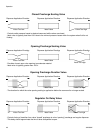
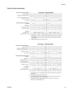
Automation Inputs (PCF Outputs)
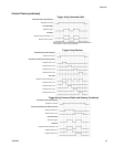
Dispense In Process
Automation Outputs (PCF Gateway Inputs)
Dispense Valve 1 Trigger
PCF State
Regulator Active (Precharge = 0)
Dispense Valve 2 Trigger
Dispense Valve 3 Trigger
Dispense Valve 1 Open
Dispense Valve 2 Open
Dispense Valve 3 Open
Trigger Using Command Cable 3x