Technical Data
3A2098H 141
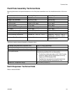
Fluid Plate Assembly Technical Data
Mounting dimensions and parts breakdowns for the fluid plate assemblies are in the installation section of this man-
ual.
*Maximum system pressure depends on dispense valve.
Swirl Dispenser Technical Data
Refer to manual 309403.
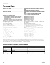
Cartridge Regulator Mastic Regulator
Regulator Manual 308647 307517
Weight - No Flow Meter 25.5 lb (11.6 kg) 33 lb (15 kg)
Weight - Helical 40 lb (18 kg) 48 lb (22 kg)
Fluid Port Inlet Helical: 3/4 in. npt(f) 3/4 in. npt(f)
Fluid Port Outlet 1/2 in. npt(f) 3/4 in. npt(f)
Maximum Fluid Working Pressure*
See Models on page 4 See Models on page 4
Air Supply 1/4 in. npt(f) 1/4 in. npt(f)
Maximum Air Working Pressure 100 psi (0.7 MPa, 7.0 bar) 100 psi (0.7 MPa, 7.0 bar)
Minimum Air Working Pressure 60 psi (410 kPa, 4.1 bar) 60 psi (410 kPa, 4.1 bar)
Fluid Operating Temperature Ambient 40° - 120°F (4° - 50°C) Heated 40° - 400°F (4° - 204°C)
Ambient 40° - 120°F (4° - 50°C)
Minimum Flow Rate - Helical Ambient 25 cc/min Heated 50 cc/min
Ambient 25 cc/min
Air outlets, open and close to dispense valve 5/32 in. (4 mm) tube fittings
Electric Power Requirements 24 Vdc or 100-240 Vac
Power Supplied to Dispense Valve Solenoid(s) 24 Vdc
Fluid Specifications
For use when dispensing fluids that meet at least one of
the following conditions for non-flammability:
• The fluid has a flash point above 140° F (60° C) and a
maximum organic solvent concentration of 20% by
weight, per ASTM Standard D93.
• The fluid does not sustain burning when tested per
ASTM Standard D4206 Sustained Burn Test.
Ambient Air Temperature Range
40° to 120° (4° to 50° C)


