


Operation
3A2098H 45
Automation Control (Normal
Operation)
During automation control (normal operation), the sys-
tem can dispense or change dispense parameters when
it receives a command from the automation unit.
The automation control operates using the concept of
jobs and styles. For a detailed explanation of jobs and
how they work within the PCF system, see Jobs on
page 45. For a detailed explanation of styles and how
they work within the PCF system, see Styles on
page 46.
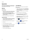
Jobs
NOTE: See Appendix D - I/O Signal Descriptions,
page 138, for automation input and output signal
descriptions.
A job is an automation sequence in which material can
be dispensed. The amount of material specified for a job
varies by application. In some applications, a job may be
the amount of material dispensed on a part. Other appli-
cations may define a job to be the amount of material
dispensed on a number of parts or dispensed over a
period of time.
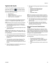
A job is initiated when the automation sends a Style
Strobe signal to the PCF. Once the job is initiated, the
PCF will start tracking the amount of volume requested
by the automation and the amount of material that is
actually dispensed. These volumes will be tracked until
the job is completed. At the end of the job, error calcula-
tions are made and the volumes are stored on the PCF
system (Job Log).
The PCF system monitors two things to determine when
a job is complete. Either the Dispense Complete signal
is sent by the automation or the job complete timer
expires. The type of job end signal is configured to
Timer or Gateway in Fluid Plate x, screen 1 (Control
Settings). If the timer method is used, the timer begins
counting every time the dispense valve is turned off. If
the valve stays off for more than the preset timer value,
the job is considered complete.
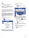
Once the job is complete, the job information is stored to
memory. The most recent jobs can be viewed on the
Job screen. The information stored with each job is as
follows. See Job Report Screens, page 114, for
instructions on how to view job reports.
Actual (Measured) Volume - The amount of material
measured by the flow meter during a job.
Requested Volume - The amount of material that the
automation tries to dispense during a job. In Bead
mode, the requested volume is calculated as the
requested flow rate multiplied by the duration of the dis-
pense. In all other modes, the requested volume is
same as the target volume.
Target Volume - The amount of material a job should
have. This is defined in the Style.
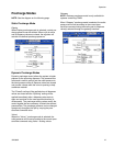
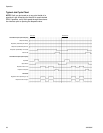
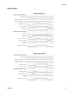
Jobs in Bead Mode
In Bead Mode, all of the previously mentioned volumes
are monitored. The High Volume, Low Volume, and
Computed Target errors are evaluated at the end of the
job. The volume alarms compare the measured volume
to the requested volume and the computed target alarm
compares the requested volume to the target volume.
Jobs in Pressure Mode
In Pressure Mode, the requested volume is not mea-
sured. In this mode, the automation command voltage
corresponds to a pressure instead of flow rate. For this
reason the requested volume is not available (as well as
the Computed Target error). The high and low volume
alarms compare the measured volume to the target vol-
ume for pressure mode.
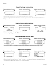
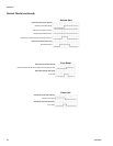
Continuously Running Applications
In some cases the target volume for a job is not known.
An example of a case where the target volume is
unknown is a continuously running system. This would
be a system that does not run jobs, but runs continu-
ously over a day or a shift. In this case, the flow rate
becomes more important than the amount of volume
dispensed in a job. The way to handle this situation is to
set the target volume to a value of zero. This effectively
disables the Computed Target error. The controls will
still maintain the desired flow rate and report errors cor-
responding to the tolerance set for the running style.