


Installation
3A2098H 23
Electrical Connections
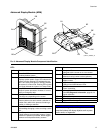
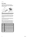
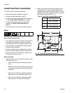
Connect Light Tower Accessory
1. Order the 255468 Light Tower Accessory as a diag-
nostic indicator for the PCF system.
2. Connect the cable from the light tower to the digital
I/O port (BS) on the ADM.
See Table 3 for a description of light tower signals.
NOTE: See Errors, page 66, for error definitions.
To reduce the risk of fire, explosion, or electric shock,
when grounding, connecting cables, connecting to a
power source or making other electrical connections:
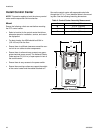
• The control center must be electrically connected
to a true earth ground; the ground in the electrical
system may not be sufficient. Refer to your local
code for the requirements for a “true earth ground”
in your area.
• All wires used for grounding must be 18 AWG min-
imum.
• A qualified electrician must complete all grounding
and wiring connections.
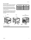
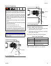
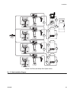
• For 24 Vdc wiring refer to F
IG
. 13.
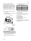
• For 100-240 Vac wiring refer to F
IG
. 14.
• Incoming power wiring must be guarded from the
enclosure. Use a protective grommet where the
power wiring enters the enclosure to prevent wear.
NOTICE
If power and grounding connections are not done
properly, the equipment will be damaged and the
warranty voided.
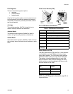
F
IG
. 13: 24 Vdc Wiring
+
-
Ground
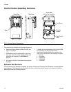
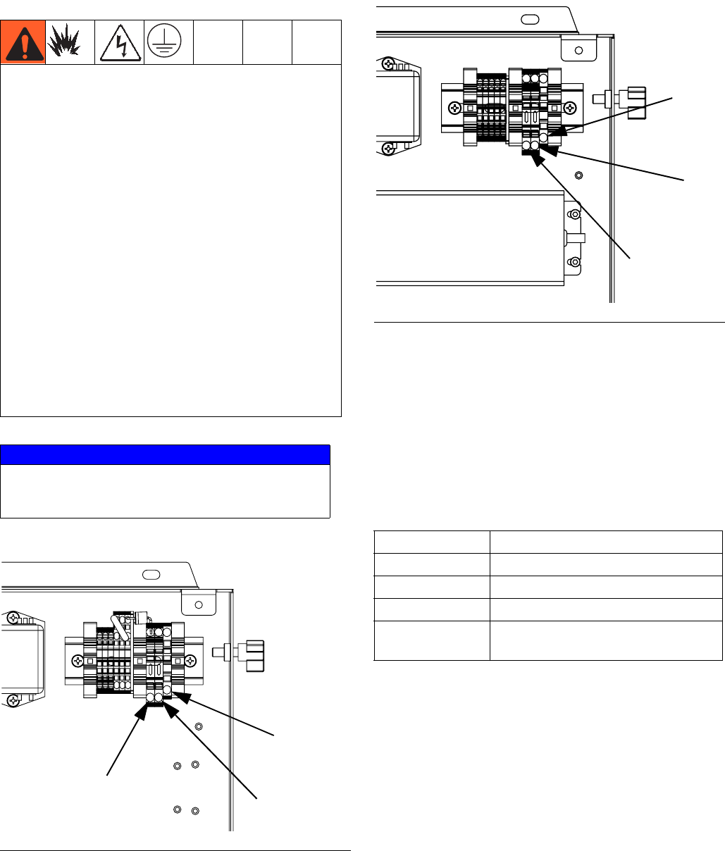
F
IG
. 14: 100-240 Vac Wiring
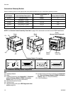
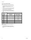
Table 3: Light Tower Signals
Signal Description
Green No errors.
Yellow An advisory exists.
Yellow flashing A deviation exists.
Red solid An alarm exists. One or more fluid
plates may be shutdown.
Ground
N
L