Installation
3A2098H 27
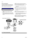
Ground
Ground the fluid plate assembly as instructed here and
in the individual component manuals. Make sure the
fluid plate assembly and its components are installed
correctly to ensure proper grounding.
Air and Fluid Hoses
For static dissipation, use only electrically conductive
hoses or ground the applicator / dispense valves.
Dispense Valve
Follow the grounding instructions in the dispense valve
manual.
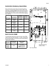
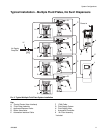
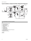
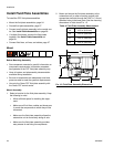
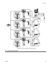
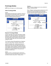
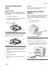
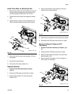
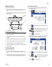
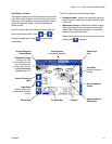
Connect Fluid and Air Lines
Follow the instructions in your separate component
manuals to connect air and fluid lines. The following are
only general guidelines.
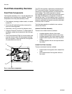
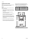
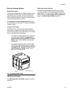
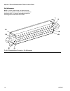
• The PCF fluid plate assembly should be installed on
the automation unit or in another appropriate place,
as close as practical to the dispense valve.
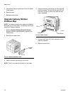
• Connect a fluid line between the fluid plate outlet and
the dispense valve. Smaller diameter and shorter
fluid lines (hoses) will provide better fluid system
response.
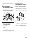
• Connect a fluid line to the flow meter fluid inlet or to
the regulator inlet if your system does not have a
flow meter.
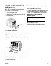
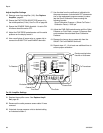
• Air must be clean and dry, between 60-120 psi
(0.41-0.82 MPa, 4.14-8.27 bar). Flush air line before
plumbing in air filter assembly (234967). Plumb in air
filter assembly near air drop site (upstream of fluid
plate module). Adding an air regulator to this line will
provide more consistent dispense valve response
times.
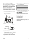
• Connect an air supply line to the 1/4 npt inlet port on
the fluid plate(s) air supply inlet.
• Connect 5/32 in. or 4 mm OD air lines from the appli-
cator's solenoid valve to the applicator. Plug any
unused solenoid ports.
NOTE: To maximize system performance keep the dis-
pense hose length and ID as small as the application
will allow.
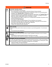
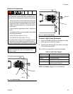
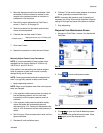
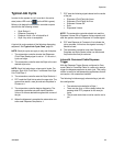
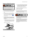
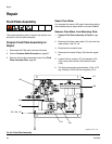
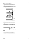
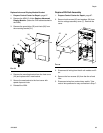
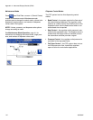
To reduce the risk of fire, explosion, or electric shock,
when grounding, connecting cables, connecting to a
power source or making other electrical connections:
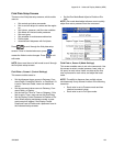
• The control center must be electrically connected
to a true earth ground; the ground in the electrical
system may not be sufficient. Refer to your local
code for the requirements for a “true earth ground”
in your area.
• All wires used for grounding must be 18 AWG min-
imum.
• A qualified electrician must complete all grounding
and wiring connections.
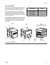
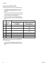
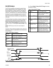
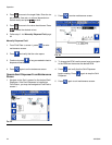
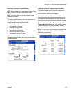
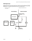
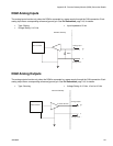
• For 24 Vdc wiring refer to F
IG
. 13.
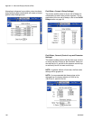
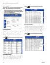
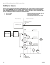
• For 100-240 Vac wiring refer to F
IG
. 14.
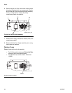
• Incoming power wiring must be guarded from the
enclosure. Use a protective grommet where the
power wiring enters the enclosure to prevent wear.
NOTICE
If power and grounding connections are not done
properly, the equipment will be damaged and the
warranty voided.
NOTICE
Route all fluid and air lines carefully. Avoid pinching
and premature wear due to excessive flexing or rub-
bing. Hose life is directly related to how well they are
supported.