


Installation
24 3A2098H
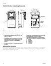
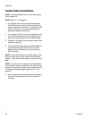
Install Fluid Plate Assemblies
To install the PCF fluid plate assemblies:
• Mount the fluid plate assemblies, page 24
• Ground fluid plate assemblies, page 27
• Connect one fluid plate assembly to the control cen-
ter. See Install Cable Assemblies on page 28.
•
If multiple fluid plates,
connect the fluid plates
together. See Install Cable Assemblies on
page 28.
• Connect fluid lines, air lines, and cables; page 27
Mount
Before Mounting Assembly
• See component manuals for specific information on
component requirements. Information presented
here pertains to the PCF fluid plate assembly only.
• Have all system and subassembly documentation
available during installation.
• Be sure all accessories are adequately sized and
pressure-rated to meet the system's requirements.
• Use only the Graco PCF fluid plate assembly with
the Graco PCF control center.
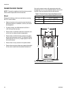
Mount Assembly
1. Select a location for the fluid plate assembly. Keep
the following in mind:
• Allow sufficient space for installing the equip-
ment.
• Make sure all fluid lines, cables and hoses eas-
ily reach the components to which they will be
connected.
• Make sure the fluid plate assembly allows the
automation unit to move freely along all axis.
• Make sure the fluid plate assembly provides
easy access for servicing its components.
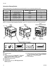
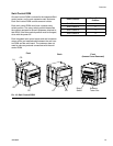
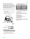
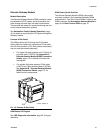
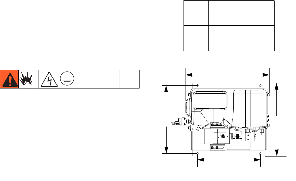
2. Mount and secure the fluid plate assembly to the
automation unit (or other mounting surface) with
appropriate size bolts through the 0.397 in. (10 mm)
diameter holes in the base plate. See the mounting
dimensions in Table 4 and F
IG
. 15.
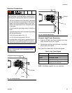
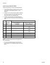
Table 4: Fluid Plate Assembly Measurement
A
16.5 in. (419 mm)
B
14.0 in. (356 mm)
C
14.4 in. (366 mm)
D
13.4 in. (340 mm)
F
IG
. 15: Fluid Plate Assembly Dimensions
A
B
C
D