


Appendix C - Communications Gateway Module (CGM) Connection Details
132 3A2098H
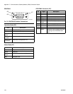
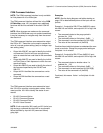
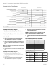
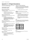
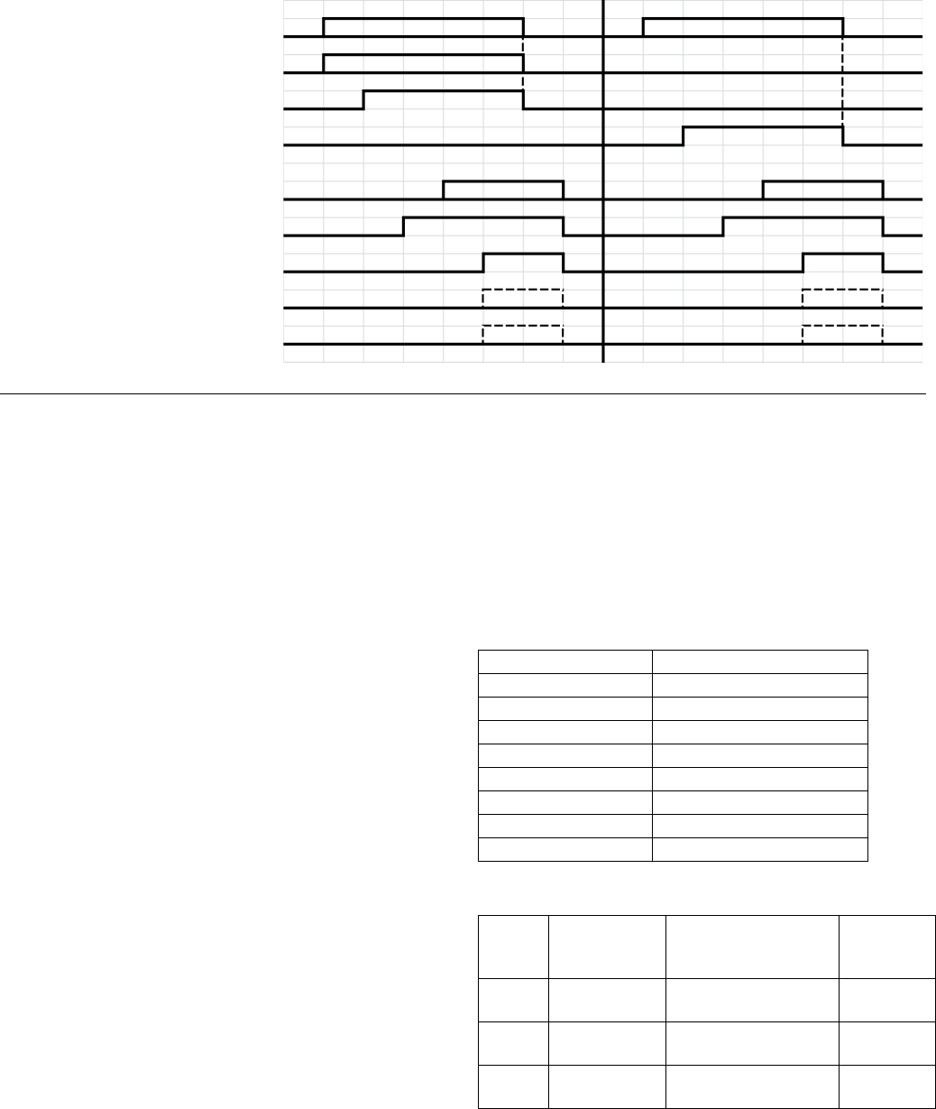
Command Interface Timing Diagram
Command Interface Write Operation
1. Set Command Identification Bits and Fluid
Plate/Swirl Identification Bits to the desired values.
2. Set Value Bits (Output) with the value that is desired
to be written.
3. Set Write Bit.
4. Wait for the Command Active Bit to become set.
This indicates that an operation is in process.
5. Wait for the Command Success Bit, Command Fail-
ure Bit, or Command Value Coerced Bit to become
set.
NOTE: The Value Bits (Input) now contain the value that
was actually written.
6. Clear the Write Bit to end the write command opera-
tion.
Command Interface Read Operation
1. Set Command Identification Bits and Fluid
Plate/Swirl Identification Bits to the desired values.
2. Set Read Bit.
3. Wait for the Command Active Bit to become set.
This indicates that an operation is in process.
4. Wait for the Command Success Bit or Command
Failure Bit to become set.
NOTE: If Command Success Bit has been set, valid
data will be present within the Value Bits (Input).
5. Clear the Read Bit to end the read command opera-
tion.
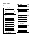
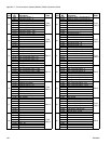
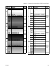
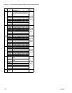
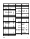
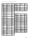
Fluid Plate/Swirl Identification Commands
Fluid Plate Commands
F
IG
. 73: CGM Command Interface Timing Diagram
Automation Inputs (PCF Outputs)
Automation Outputs (PCF Inputs)
Command Bits 256-275
Value Bits 288-319
Write Bit 321
Read Bit 320
Value Bits 128-159
Command Active Bit 160
Command Success Bit 161
Command Failure Bit 162
Command Value Coerced Bit 163
Bits Set
Bits Set
Bits Set
Bits Set
Bits Set
Write Command
Read Command
Output Bits 268-275 Description
0xB0 Fluid Plate 1
0xB1 Fluid Plate 2
0xB2 Fluid Plate 3
0xB3 Fluid Plate 4
0xE1 Swirl 1
0xE2 Swirl 2
0xE3 Swirl 3
0xE4 Swirl 4
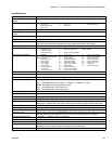
Output
Bits
256-267 Description
Units
*See Units
Definitions, page 137
Read or
Write
0x004 Software Part
Number
STR_3_0 Read Only
0x005 Software Part
Number
STR_7_4 Read Only
0x006 Software Part
Number
STR_11_8 Read Only