


Overview
18 3A2098H
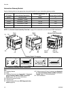
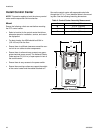
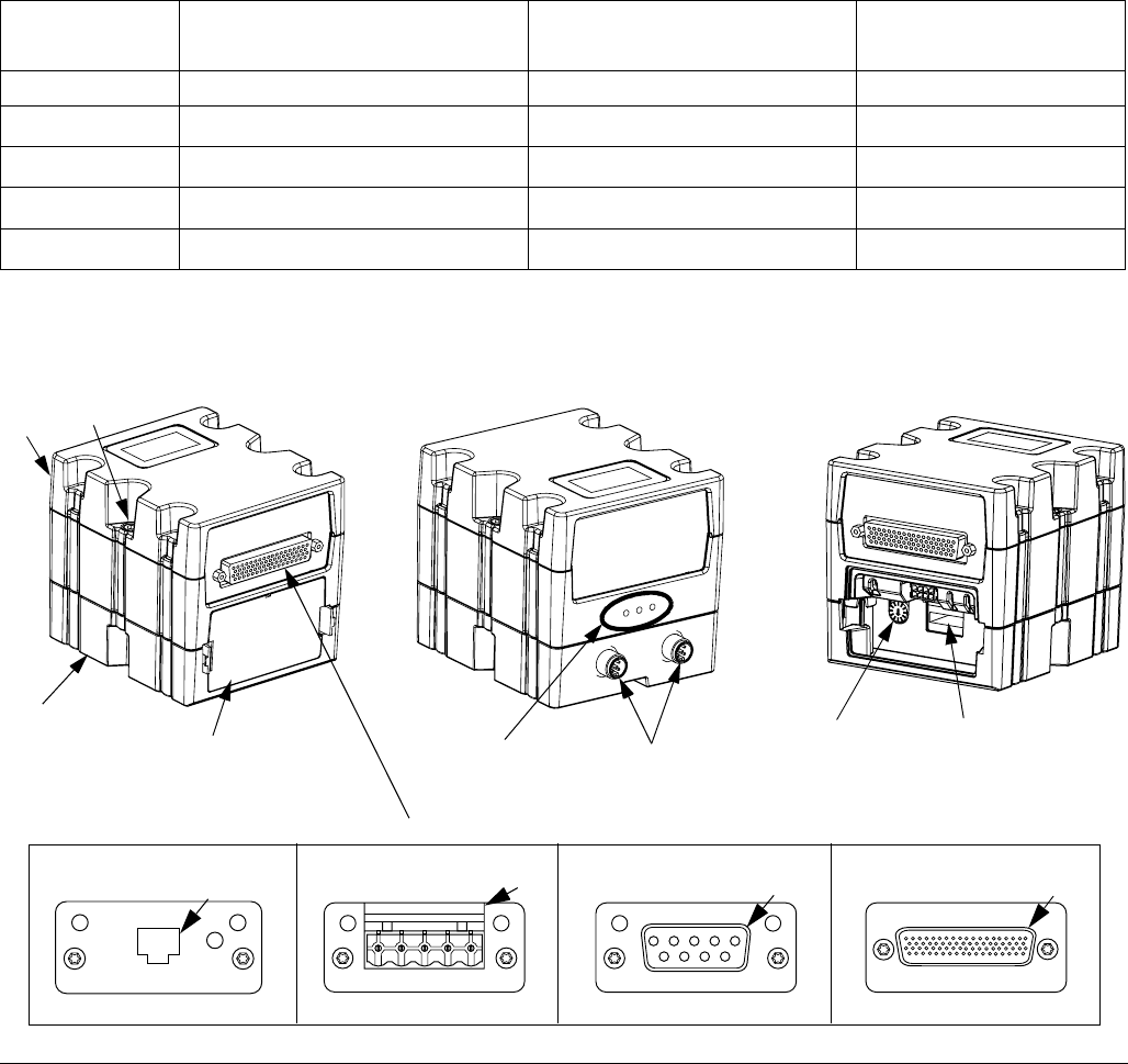
Automation Gateway Module
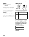
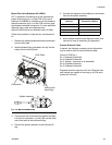
See the following table for the appropriate rotary switch position for your automation gateway module.
NOTE: See Control Center Assembly Overview on page 16 for automation and swirl control DGM identification.
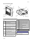
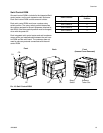
Key:
CA Gateway Module
CB Base
CC Fieldbus Connector (see Appendix C - Communi-
cations Gateway Module (CGM) Connection
Details, page 122, for more information)
CD Module Connection Screws
CE Access Cover
CF Module Status LEDs (see LED Diagnostic Infor-
mation, page 65)
CG D-Subminiature (D-Sub) Connector (see Appendix
B - Discrete Gateway Module (DGM) Connection
Details, page 115, for pinout details)
CH CAN Connectors
PCF Model User Interface Description
Gateway Part Number To
Order Rotary Switch Position
PFxx0x Discrete (DGM) 24B681 0
PFxx1x
DeviceNet
™
(CGM)
15V759 Any
PFxx2x
EtherNet/IP
™
(CGM)
15V760 Any
PFxx3x
PROFIBUS
™
(CGM)
15V761 Any
PFxx4x
PROFINET
™
(CGM)
15V762 Any
F
IG
. 9: Automation Gateway Module Components
TI11816A
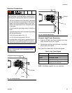
PROFIBUS
Discrete
CG
CC
TI11814A
TI11815A
CA
CD
Gateway Module Connectors
CB
PROFINET or EtherNet/IP
DeviceNet
CE
CF
CH
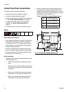
Front Back
CC
CC
Rotary
Switch
Software
Token Slot
Front
(Access Cover Removed)