Appendix A - Advanced Display Module (ADM)
3A2098H 107
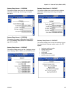
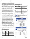
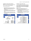
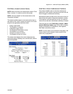
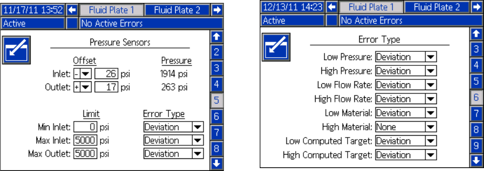
Fluid Plate x, Screen 5 (Pressure Sensors)
NOTE: Inlet sensor settings will be grayed out on this
screen for systems with heated fluid plates.
This screen enables users to:
• Set the offset for the inlet and outlet pressures.
NOTE: The offset value must be set to a non-zero
value before ‘-’ can be selected from the +/-
drop-down menu.
• Set the minimum and maximum pressure limits for
the inlet, and the maximum pressure limit for the
outlet.
• Set the error type (alarm or deviation) that will be
issued if the inlet and/or outlet pressure go outside
of the set limits.
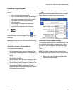
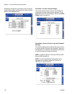
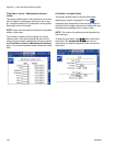
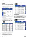
Fluid Plate x, Screen 6 (Error Type)
This screen enables users to set the error type (none,
alarm, or deviation) that will be issued if the pressure,
flow rate, volume, or computed target goes outside the
tolerance settings of the active style. See Configure
Errors on page 36.
NOTE: Only the low/high pressure errors will be
enabled for systems without a flow meter.
• The pressure and flow rate errors are relative to the
value commanded (through the command cable,
gateway or display)
• The volume is relative to the requested volume and
computed target errors are relative to the target vol-
ume defined in the style


