


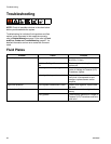

Troubleshooting
3A2098H 65
Gateway Module
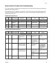
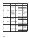
LED Diagnostic Information
The following LED signals, diagnosis, and solutions apply to the Advanced Display Module, Fluid Control Module,
and Gateway module.
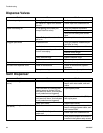
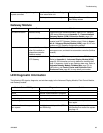
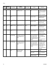
Motor not responding to change in
speed command
No “Swirl Speed Command” signal
from automation unit
Check input from automation unit
Swirl speed source incorrectly set Verify Speed Command Source in
Swirl Setup screen
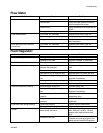
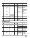
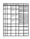
Problem Cause Solution
No communication Incorrect wiring Check wiring per fieldbus standard. Refer to PCF Gateway
LED status indicators and Appendix C - Communications
Gateway Module (CGM) Connection Details, page 122.
Incorrect fieldbus settings Confirm fieldbus settings at automation controller (fieldbus
master) and PCF Gateway (fieldbus slave). Refer to Appen-
dix A - Advanced Display Module (ADM), page 99, for infor-
mation on PCF Gateway configuration settings.
Incorrect data
Incorrect fieldbus configu-
ration file installed on
automation controller
(fieldbus master)
Download PCF fieldbus configuration file from
www.graco.com, and install on automation controller (fieldbus
master).
Incorrect map installed on
PCF Gateway
Confirm correct PCF data map is installed on PCF Gateway.
Refer to Appendix A - Advanced Display Module (ADM),
page 99, for information on how to determine installed data
map. If necessary, install a new Gateway data map. Refer to
Upgrade Gateway Module Fieldbus Map, page 78, for
instructions, and Control Center and Expansion Swirl
Enclosure Parts, page 92, for map token part number.
Module Status LED Signal Diagnosis Solution
Green on System is powered up -
Yellow Internal communication in progress -
Red solid Hardware failure Replace module
Red flashing fast Uploading software -
Red flashing slow Token error Remove token and upload software
token again.
Red flashes three times, pauses,
then repeats
Invalid rotary switch position (FCM
and DGM only)
Change rotary switch position to a
valid position then restart the system.
See page 15.