


ii
6-3-2 Type configuration .......................................................................................... 6-7
6-3-3 List of specifications........................................................................................ 6-7
6-3-4 Outline dimensions ......................................................................................... 6-8
6-3-5 Explanation of connectors .............................................................................. 6-8
6-3-6 Installation....................................................................................................... 6-9
Chapter 7 Installation
7-1 Installation of the linear servomotor .................................................................... 7-2
7-1-1 Environmental conditions................................................................................ 7-3
7-1-2 Installing the linear servomotor....................................................................... 7-3
7-1-3 Cooling of linear servomotor........................................................................... 7-4
7-2 Installation of the servo amplifier ......................................................................... 7-5
7-2-1 Environmental conditions................................................................................ 7-5
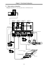
7-2-2 Drive section wiring system diagram .............................................................. 7-6
7-2-3 Installing the unit............................................................................................. 7-7
7-2-4 Layout of each unit ......................................................................................... 7-8
7-2-5 Main circuit connection ................................................................................... 7-9
7-2-6 Connection of feedback cable ........................................................................ 7-11
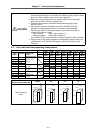
7-2-7 Link bar specifications .................................................................................... 7-12
7-2-8 Separated layout of units ................................................................................ 7-13
7-2-9 Installing multiple power supply units ............................................................. 7-14
7-2-10 Installation for 2ch communication specifications with CNC, and
installation of only one power supply unit ..................................................... 7-16
7-2-11 Connection of battery unit............................................................................. 7-17
7-2-12 Connection with mechanical brakes ............................................................. 7-18
Chapter 8 Drive Section Connector and Cable Specifications
8-1 Cable connection system ...................................................................................... 8-2
8-1-1 Cable option list .............................................................................................. 8-3
8-2 Cable connectors ................................................................................................... 8-5
8-2-1 Servo amplifier CN1A, CN1B and CN9 cable connector ................................ 8-5
8-2-2 Servo amplifier CN2 and CN3 cable connector .............................................. 8-5
8-2-3 Servo amplifier CN20 connector (for mechanical brakes) .............................. 8-5
8-2-4 MDS-B-HR, MDS-B-MD cable connector ....................................................... 8-6
8-2-5 Power supply section power wire connector................................................... 8-7
8-2-6 Flexible conduits ............................................................................................. 8-10
(1) Method for connecting to a connector with back shell............................... 8-10
(2) Method for connecting to the connector main body .................................. 8-10
8-3 Cable clamp fitting ................................................................................................. 8-11
8-4 Cable wire and assembly....................................................................................... 8-12
8-5 Cable connection diagram..................................................................................... 8-13
8-5-1 CNC unit bus cable......................................................................................... 8-13
8-5-2 Absolute value scale coupling cable............................................................... 8-14
8-5-3 Cable for amplifier – scale I/F unit .................................................................. 8-15
8-5-4 Cable for scale I/F unit – scale ....................................................................... 8-16
8-5-5 Cable for scale I/F unit – pole detector ........................................................... 8-17
8-5-6 Cable for I/F unit – motor thermal ................................................................... 8-17
8-5-7 Mechanical brake cable .................................................................................. 8-18
Chapter 9 Setup
9-1 Initial setup of servo drive unit ............................................................................. 9-2
9-1-1 Setting the rotary switches.............................................................................. 9-2
9-1-2 Transition of LED display after power is turned ON........................................ 9-2
9-2 Setting the initial parameters ................................................................................ 9-3
9-2-1 Setting the initial parameters .......................................................................... 9-3