


Chapter 2 Drive System Configuration
2–6
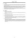
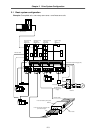
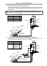
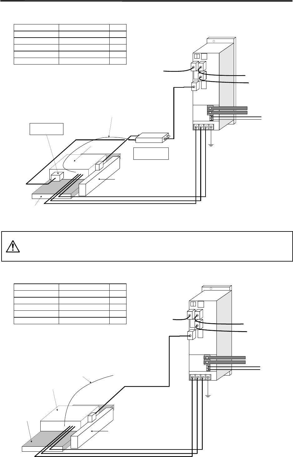
(1) Standard incremental system
MDS-B-V14L
Servo driver
To next axis,
terminator or
battery unit
To power
supply if final
axis
Empty
CON3
CON4
CON1
CON2
CN1A
CN2
CN4
CN3
To NC or
previous axis
CN1B
Scale I/F
(MDS-B-HR-11M)
Linear motor
primary side
Linear motor secondary
side permanent magnet
Pole detector
(MDS-B-MD-600)
Analog voltage output type
incremental scale
(LS186,LIDA181,LIF181,etc.)
L+
L–
Single-phase
200VAC
UV W
Motor thermal
signal
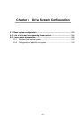
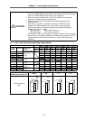
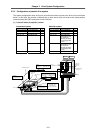
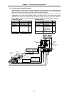
(2) Absolute system (System using linear scale LC191M)
CAUTION
In a system that does not use the MDS-B-HR unit (scale I/F unit), use the
motor thermal signal for the CNC unit's general-purpose input port, and detect
the motor overheating.
MDS-B-V14L
Servo driver
To NC general-
purpose input port
LC191M (Heidenhain)
Absolute position linear scale
To next axis,
terminator or
battery unit
To power
supply if final
axis
To NC or
previous axis
Linear motor
primary side
Linear motor
secondary side
permanent
magnet
Motor thermal
signal
CN1A
CN1B
CN4
CN3
CN2
L+
L–
Single-phase
200VAC
U V W
Unit name Type Qty.
Linear servomotor LM-NP- 1
Servo driver MDS-B-V14L- 1
Linear scale LS186, LIDA181 etc. 1
Scale I/F unit MDS-B-HR-11M 1
Pole detection unit MDS-B-MD-600 1
Unit name Type Qty.
Linear servomotor LM-NP- 1
Servo driver MDS-B-V14L- 1
Linear scale LC191M 1
Scale I/F unit None 0
Pole detection unit None 0