


Chapter 10 Adjustment
10–13
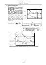
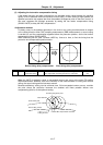
(2) Adjusting the speed loop leading compensation (VIA)
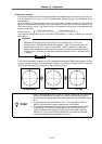
The VIA has a large influence on the position trackability, particularly during high-speed cutting
(generally F1000 or more). Raising the setting value improves the position trackability, and the
contour precision during high-speed cutting can be improved. For high-speed high-precision
cutting machines, adjust so that a value equal to or higher than the standard value can be set.
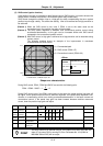
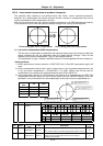
When the VIA is set lower than the standard value and set to a value differing between
interpolation axes, the roundness precision may become worse (the circle may distort). This is
due to differences occurring in the position trackability between interpolation axes. The distortion
can be improved by matching the VIA with the smaller of the values. Note that because the
position trackability is not improved, the surface precision will not be improved.
(Refer to "10-2-2 (2) Setting the speed loop leading compensation")
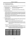
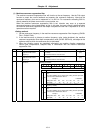
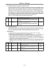
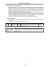
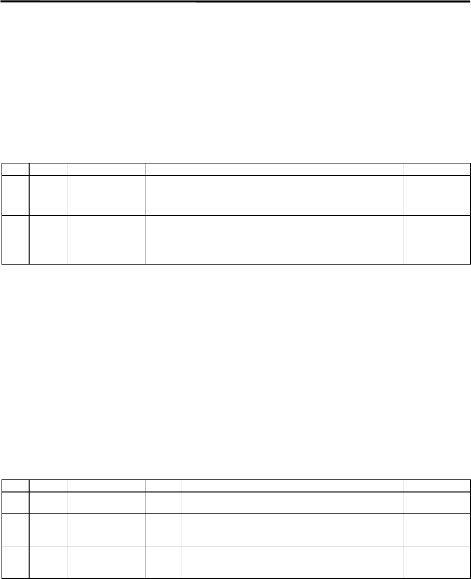
No. Abbrev. Parameter name Explanation Setting range
SV005 VGN1 Speed loop gain
Increase the value by 10 to 20% at a time.
If the machine starts resonating, lower the value by 20 to 30% at a time.
The setting value should be 70 to 80% of the value where resonance
does not occur.
1 to 999
SV008 VIA Speed loop leading
compensation
1364 is set as a standard. 1900 is set as a standard during SHG
control. Adjust in increments of approx. 100.
Raise the VIA and adjust to improve the contour tracking precision in
high-speed cutting. If the position droop vibrates (10 to 20Hz), lower the
VIA and adjust.
1 to 9999
(0.0687rad/s)
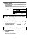
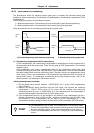
(3) Disturbance observer
The disturbance observer can reduce the effect caused by disturbance, frictional resistance or
torsion vibration during cutting by estimating the disturbance thrust and compensating it. It also is
effective in suppressing the vibration caused by speed leading compensation control.
<Setting method>
1) Adjust VGN1 to the value where vibration does not occur, and then lower it 10 to 20%.
2) Set the total movable mass (including motor mass) (SV037: JL).
3) Set the observer filter band (observer pole) in the disturbance observer 1 (SV043:OBS1), and
estimate the high frequency disturbance to suppress the vibration. Set 600 as a standard.
4) Set the observer gain in disturbance observer 2 (SV044:OBS2). The disturbance observer will
function here for the first time. Set 100 first, and if vibration does not occur, increase the
setting by 50 at a time to increase the observer effect.
5) If vibration occurs, lower OBS1 by 50 at a time. The vibration can be eliminated by lowering
OBS2, but the effect of the disturbance observer can be maintained by keeping OBS2 set to a
high value.
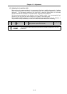
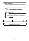
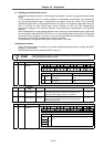
No. Abbrev. Parameter name Unit Explanation Setting range
SV037 JL Total movable mass kg Set the total mass of the moving section with a kg unit.
(Including the motor mass)
0 to 5000
(kg)
SV043 OBS1 Disturbance
observer 1
rad/s Set the observer filter band (observer pole).
Set 600 as a standard, and lower the setting by 50 at a time if
vibration occurs.
0 to 1000
(rad)
SV044 OBS2 Disturbance
observer 2
% Set the observer gain.
Set 100 to 300 as a standard, and lower the setting if
vibration occurs.
0 to 500
(%)