


Chapter 2 Drive System Configuration
2–4
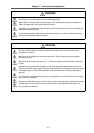
CAUTION
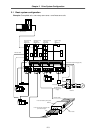
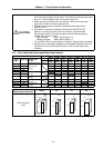
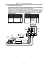
1. In a system having a spindle drive unit, always place the spindle drive unit
next to the power supply unit as shown in the drawing. Also, place the servo
drive unit 11kW and above next to the power supply unit.
2. When also using a spindle drive unit, place the units next to the power
supply unit in order of the drive capacity size.
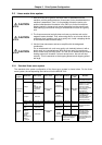
3. The use of the contactor installation can be selected except for the
MDS-B-CV-370.
4. Use without a contactor is possible, except for the MDS-B-CV-370.
However, for safety purposes, use of a contactor is recommended.
Set the rotary switch on the power supply unit as follows according to
whether the contactor is used.
With contactor Rotary switch setting = 0
Without contactor Rotary switch setting = 1
For the MDS-A-CR, the rotary switch is fixed to 0. Always install a contactor.
5. Always install an AC reactor (shipped from Mitsubishi). Note that this is not
required for the A-CR. Wire the AC reactor to the front (NF side) of the
contactor.
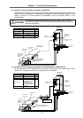
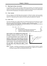
2-2 List of units and corresponding linear motors
Linear servo amplifier Corresponding servo amplifier (LM-
)
Type
NP2S-05
M
NP2M-1
0M
NP2L-15
M
NP4S-10
M
NP4M-2
0M
NP4L-30
M
NP4G-4
0M
Type
MDS-B-
Capacity
Outline
H×W×D (mm)
Outline
dimension types
Max.
thrust
1500N 3000N 4500N 3000N 6000N 9000N 12000N
V14L-01 0.1kW
V14L-03 0.3kW
V14L-05 0.5kW
V14L-10 1.0kW
380×60×180
A0 type
V14L-20 2.0kW
V14L-35 3.5kW
380×60×300
A1 type
V14L-45 4.5kW
380×90×300
B1 type
V14L-70 7.0kW
V14L-90 9.0kW
380×120×300
C1 type
V14L-110 11.0kW
V14L-150 15.0kW
380×150×300
D1 type
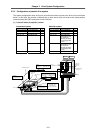
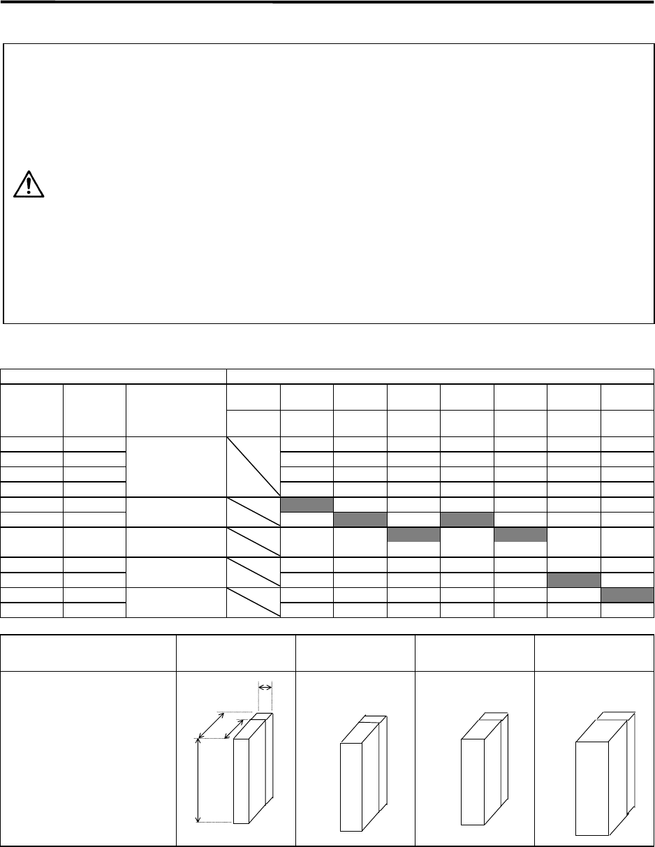
Outline dimension and
outline type of each unit
A0/A1 B1 C1 D1
Outline drawing
(mm)
W:60
Fin section D:120
D:300
180
H:380
Fin
T
he A0 type does not have
a
fin. (Depth 180)
W:90
Fin 120
D:300
H:380
W:120
Fin 120
D:300
H:380
W:150
Fin 120
D:300
H:380