


Chapter 11 Troubleshooting
11–21
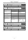
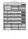
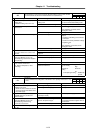
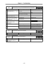
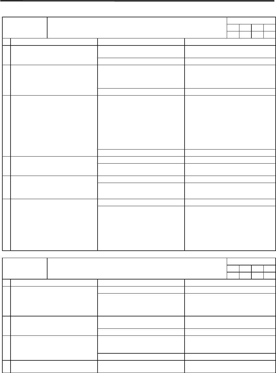
Alarm check timing
f1 f2 f3 f4
Alarm No.
50
Overload 1:
The servomotor or servo driver load level obtained from the motor current reached
the overload level set with the overload detection level (SV022:OLL).
–
{ { {
Investigation details Investigation results Remedies
The value differs from the standard
setting value.
When not using special specifications, set
the value to the standard setting value.
1 Check the servo parameter (OLL)
setting value.
Standard setting value OLL: 150.
The value is the standard setting value. Investigate item 2.
The motor is hot. Ease the operation pattern.
↓
If the problem is not solved, check
investigation item 3.
2 Check the motor temperature when the
alarm occurs.
The motor is not high. Investigate item 3.
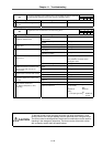
The motor is hunting. Refer to the adjustment procedures and
readjust.
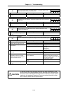
•
Check the cable wiring and connector
connection.
•
Check for incorrect parameter settings.
•
Adjust the gain.
↓
If the problem is not resolved, check
investigation item 4.
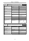
3 Check whether the motor is hunting.
The motor is not hunting. Investigate item 4.
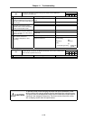
The alarm is on the unit side. Replace the drive unit. 4 Connect to another normal axis unit,
and check whether the fault is on the
unit side.
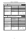
The alarm occurs even when the unit is
replaced.
Investigate item 5.
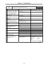
An abnormal value is displayed. Check the machine system. 5 Check whether the current value on the
CNC Servo Monitor screen is an
abnormally large value when stopped
and operating.
A correct value is displayed. Investigate item 6.
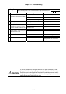
No abnormality is found in particular. Replace the motor (the detector). 6 Check if there is any abnormality in the
unit's ambient environment.
(Ex. Ambient temperature, noise,
grounding)
An abnormality was found in the
ambient environment.
Take remedies according to the causes of
the abnormality.
Ex. High
temperature ... Check the
cooling
fan.
Incomplete grounding …. Additionally
ground.
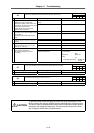
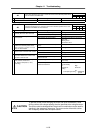
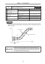
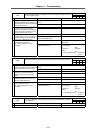
Alarm check timing
f1 f2 f3 f4
Alarm No.
51
Overload 2:
A current command exceeding 95% of the driver's max. capacity continued for 1 sec.
or more.
– –
{
–
Investigation details Investigation results Remedies
The voltage is being supplied. Investigate item 3. 1 Check whether the PN power is
supplied to the driver.
•
Check the axis for which the alarm is
occurring and the axis farthest from
the power supply.
The voltage is not being supplied. Investigate item 2.
There is no voltage at the PN terminal.
(The lamp is not lit.)
Check the power supply unit. 2 Check whether the power supply unit's
CHARGE lamp is lit, and the PN
terminal voltage.
There is voltage at the PN terminal. Check the PN wiring between the units.
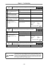
The max. value is exceeding the x level
given on the previous page.
Increase the acceleration/deceleration
time constant to lower to approx. 80% of
the limit value.
3 Check whether the current value on the
CNC Servo Monitor screen is an
abnormally large value during
acceleration/deceleration.
A correct value is displayed. Investigate item 4.
4 Check items 3 and following for alarm
No. "50".