


Chapter 10 Adjustment
10–16
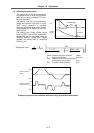
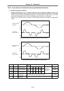
(2) Unbalance thrust compensation
If the load force differs in the positive and negative directions such as with a vertical axis or slant
axis, the thrust offset (SV032:TOF) is set to carry out accurate lost motion compensation.
<Setting method>
Measure the unbalance thrust. Carry out reciprocation operation (approx. F1000) with the axis to
be compensated and measure the load current % when fed at a constant speed on the CNC
servo monitor screen. The unbalance thrust at this time is expressed with the following
expression.
Unbalance thrust =
(+ feed load current %) – (– feed load current %)
2
The unbalance thrust value above is set for the thrust offset (TOF).
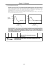
If there is a difference in the protrusion amount according to the direction, make an adjustment
with LMC2. Do not adjust with TOF.
Assume that the load current % was −40% in the + direction and −20% in the –
direction when JOG feed was carried out at approx. F1000. The unbalance thrust is
as shown below, so −30% is set for TOF.
−
40 + (
−
20)
2
= 30%
No. Abbrev.
Parameter
name
Unit Explanation Setting range
SV032 TOF Thrust offset Stall % (rated
current %)
Set this when carrying out lost motion compensation.
Set the unbalance thrust amount.
–100 to 100
POINT
Even when TOF is set, the thrust output characteristics of the motor and load
current display of the CNC servo monitor will not change.
Only LMC compensation characteristics are affected.
(Example)