


Chapter 7 Installation
7–16
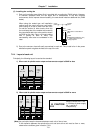
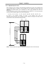
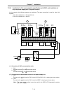
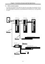
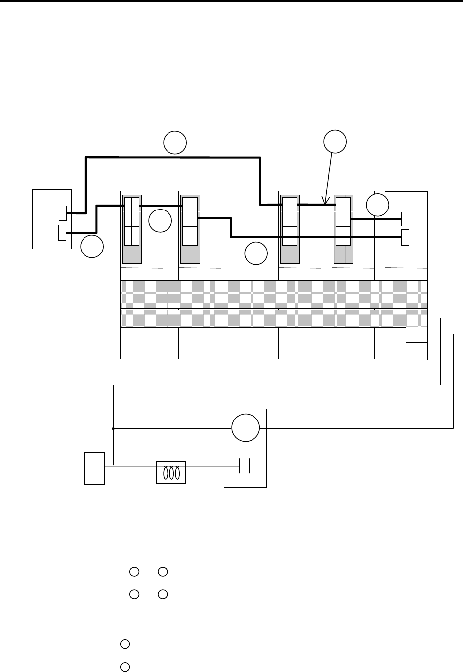
7-2-10 Installation for 2ch communication specifications with CNC, and installation of
only one power supply unit. (2-system control)
In this example, the following systems are explained. The same connection is used for other 2ch
systems.
• CH1: B-V14/V24/V14L + B-V14/V24/V14L
• CH2: B-V14/V24/V14L + A/B-SP
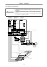
NC
B-V14L
B-V14/V24
CN1A
CN1BCN4
CH1
CH2
CN1A
CN1BCN4
CN1A
CN1BCN4
CN1A
CN1BCN4
CN4CN9
L+, L–
L1+, L1–
MC1
MC
AC reactor
(A/B-AL)
ContactorNFB1
200VAC
1
B-V14L
B-V14/V24
B-V14L
B-V14/V24
A-SP
B-SP
A-CV
B-CV
2
3
4
6
5
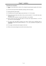
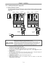
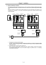
(1) Connection of CNC communication cable
1. CH1
Connect with the
1
to
2
line shown above.
2. CH2
Connect with the
3
to
4
line shown above.
(2) Communication cable between drive unit and power supply unit
1. CH1
Connect to the
5
line from the CH1 final axis (B-V14/V24/V14L in drawing) as shown above.
2. CH2
Connect to the
6
line from the CH1 final axis (A/B-SP in drawing) as shown above.
Note: The above usage method cannot be used for the MDS-A-CR (regenerative resistor
type power supply).