


Chapter 7 Installation
7–14
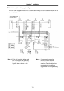
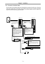
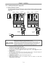
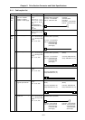
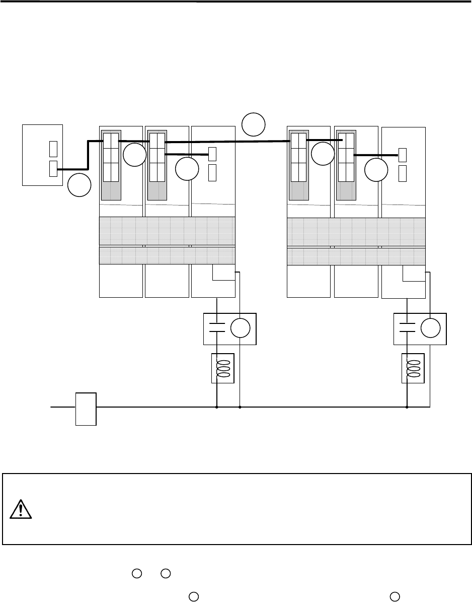
7-2-9 Installing multiple power supply units
(1) When not sharing a contactor
The following system will be explained here as a main example of installing multiple power supply
units without sharing a contactor. This same connection is used in other systems using multiple
supply units.
CN1A
CN1BCN4
CN1A
CN1BCN4
NC
B-V14L
B-V14/V24
CH1
CH2
CN1A
CN1BCN4
CN1A
CN1BCN4
CN4CN9
L+, L–
L1+. L1–
MC1
AC reactor
(A/B-AL)
Contactor
NFB1
200VAC
1
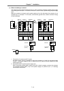
B-V14L
B-V14/V24
B-V14L
B-V14/V24
A-SP
B-SP
A-CV(NO.2)
B-CV
2
3
4
6
5
CN4CN9
L+, L–
L1+, L1–
MC1
A-CV(NO.1)
B-CV
MC MC
AC reactor
(A/B-AL)
Contactor
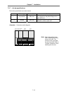
CAUTION
Always use this wiring when using the MDS-B-CV-370.
The MDS-B-CV-370 has a different rush circuit and contactor operation
sequence from the other power supply units (A/B-CV), so the contactor must
be installed independently. The unit could be damaged if the contactor is
omitted, or if the contactor is shared with other power supply units.
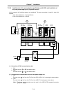
1. Connection of CNC communication cable
Connect with the
1
to
4
line shown above.
2. Connection of communication cable between drive unit and power supply unit
As shown above, connect the
5
cable to power supply unit No. 1 and the
6
cable to power
supply unit No. 2.
3. Connection of L+, L–, L1+, L1–
As shown above, connect the link bar for the power supply unit No. 1 and power supply unit
No. 2 independently. Do not short circuit both link bars and connect.
4. Connection of AC reactor
Independently install one AC reactor for each power supply unit.
5. Connection of contactor
When using the MDS-B-CV-370, the contactors cannot be shared, so install each
independently as shown above.