


Chapter 7 Installation
7–15
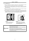
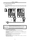
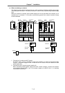
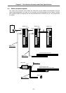
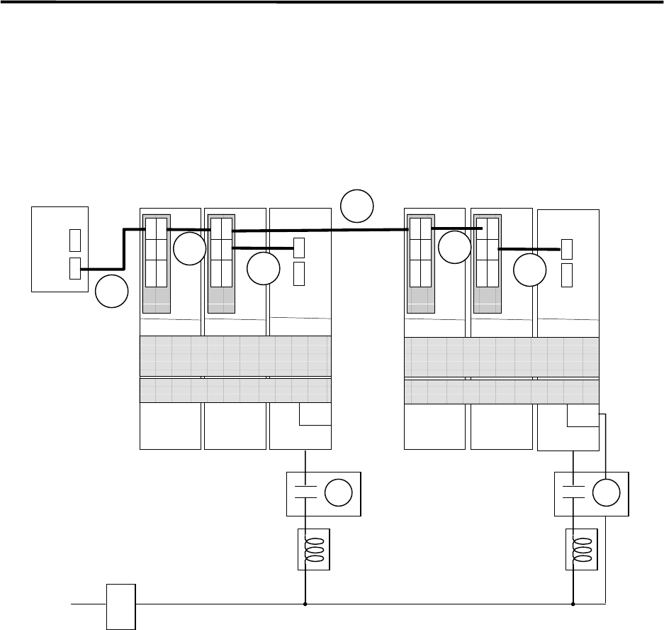
(1) When not sharing a contactor
The following system will be explained here as a main example of installing multiple power supply
units sharing one contactor. This same connection is used in other systems using multiple supply
units.
When the contactor is shared, set the power supply unit on the side where the contactor is not
controlled as "no contactor". In this case, some alarms (ground fault, external contactor fusing)
will be invalidated.
CN1A
CN1BCN4
CN1A
CN1BCN4
NC
B-V14L
B-V14/V24
CH1
CH2
CN1A
CN1BCN4
CN1A
CN1BCN4
CN4CN9
L+, L–
L1+, L1–
MC1
AC reactor
(A/B-AL)
Contactor
NFB1
200VAC
1
B-V14L
B-V14/V24
B-V14L
B-V14/V24
A-SP
B-SP
A-CV(NO.2)
B-CV
2
3
4
6
5
CN4CN9
L+, L–
L1+, L1–
MC1
A-CV(NO.1)
B-CV
MC
MC
AC reactor
(A/B-AL)
Contactor
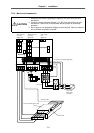
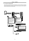
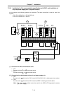
1. Connection of contactor and AC reactor
As shown above, control is possible by using one contactor in a batch for the power supply
unit No. 1 and power supply unit No. 2. Note that one AC reactor must be installed for each
power supply unit.
2. Connection of MC1 terminal (power supply unit)
When controlling multiple power supply units with a batch contactor, connect the contactor
coil excitation terminal (MC1) only to the power supply unit (A/B-CV (No. 1) in drawing)
connected to the last axis.