


Chapter 9 Setup
9–13
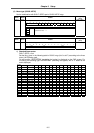
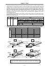
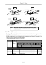
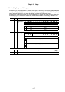
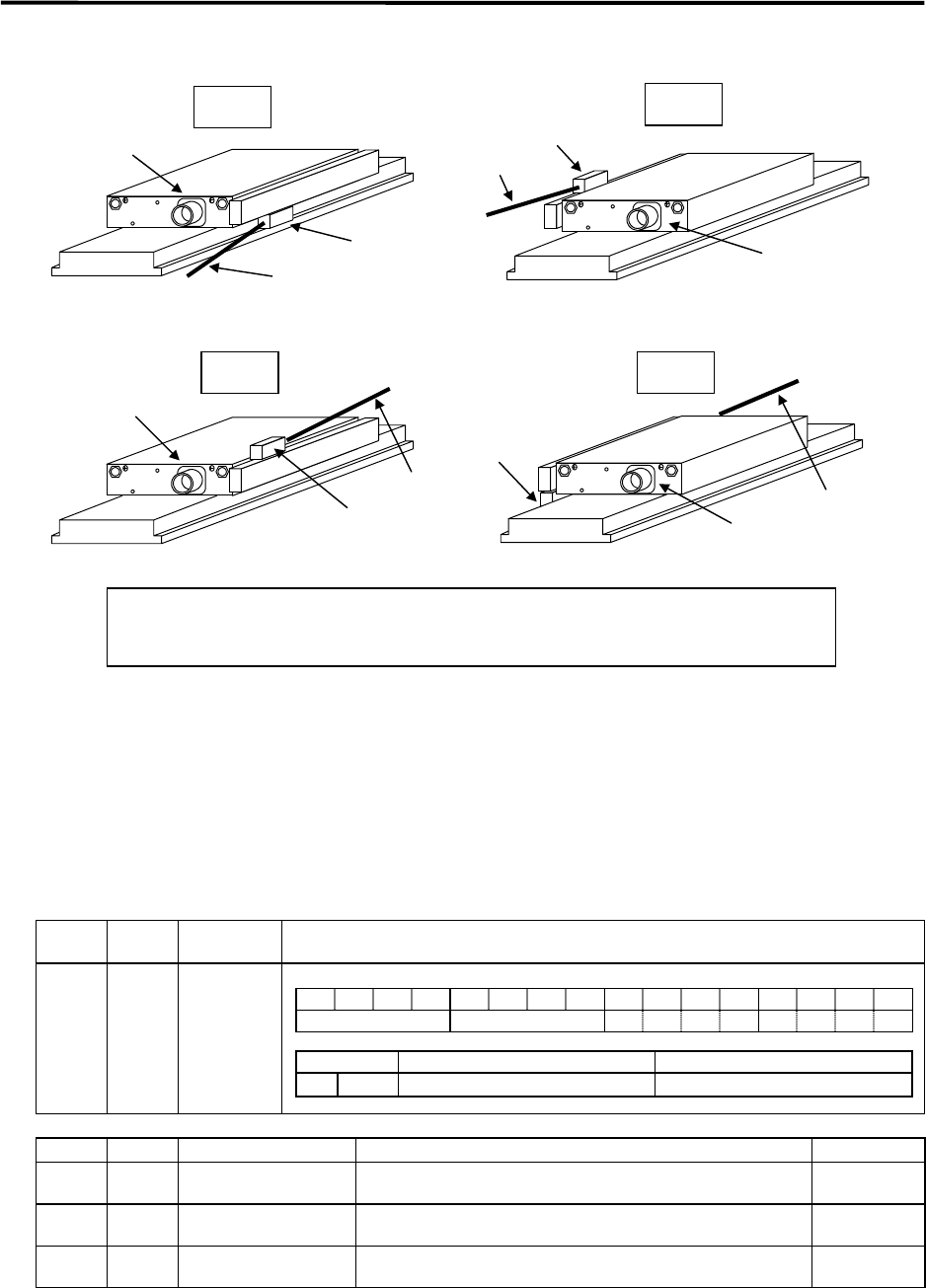
(1)
(3) (4)
(2)
Power line
connector
Detection head
Signal cable
Power line
connector
Detection head
Signal cable
Power line
connector
Detection head
Signal cable
Power line
connector
Detection head
Signal cable
Fig. 9.3.2 When linear scale body is installed on motor's primary side
(This is for the AT342. The signal cable direction is reversed for the
Heidenhain scale.)
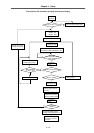
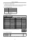
9-3-2 DC excitation function
By using the DC excitation function, the linear motor can be moved to the 0° pole regardless of the
feedback from the linear scale.
This DC excitation function is required to determine the magnetic pole shift amount. When determining
the pole shift amount, carry out DC excitation after confirming that the cycle counter displayed on the
CNC Servo Monitor screen is not 0 (Z phase passed).
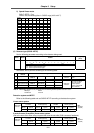
The following parameters are used for DC excitation.
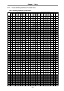
No. Abbrev.
Parameter
name
Explanation
SV034 SSF3 Special
servo
function
selection 3
This is a HEX setting parameter. Set this as follows according to the servo specification.
No. Abbrev. Parameter name Explanation Setting range
SV061 DA1NO D/A output channel 1·
data No.
Set the initial excitation level for DC excitation.
Set a minus value. Set –250 when starting DC excitation.
–32768 to
32767
SV062 DA2NO D/A output channel 2·
data No.
Set the final pole level for DC excitation.
Set a minus value. Set –250 when starting DC excitation.
–32768 to
32767
SV063 DA1MPY D/A output channel 1·
output scale
Set the initial excitation time for DC excitation. (ms)
Normally, 500 is set.
–32768 to
32767
Set so that each setting value with |SV061| ≤ |SV062| is a minus value.
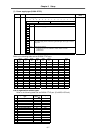
15 14 13 12 11 10 9 8 7 6 5 4 3 2 1 0
ovsn linN toff os2 dcd test mohn has2 has1
Bit Meaning when "0" is set Meaning when "1" is set
4 dcd
Setting for normal use
DC excitation mode