Chapter 9 Setup
9–4
(2) Servo specifications (SV017: SPEC)
The following parameters are set according to the system specifications such as the servomotor
type, motor and driver (servo drive unit) combination, and absolute position system or incremental
position system, etc.
Name Abbrev. Details
Setting range
(unit)
SV017 SPEC
Servo specifications
HEX setting
(3) Ball screw pitch (SV018: PIT)
SV018 PIT
Set the magnetic pole pitch.
The pole pitch is determined by the motor type.
Refer to 9-2-4 List of standard parameters for each motor.
1 to 32767
(mm)
(4) Detector resolution (SV019: RNG1, SV020: RNG2)
Set the following parameters according the detector resolution.
SV019 RNG1 Set the resolution per magnetic pole pitch of the detector used for position control.
1 to 9999
(Kp/PIT)
SV020 RNG2 Set the resolution per pole pitch of the detector used for speed control.
1 to 9999
(Kp/PIT)
Linear motor system
AT342 LC191M
HR+incre-ment
al scale∗3
HR+AT342
∗3
RNG1 RNG2 RNG1 RNG2 RNG1 RNG2 RNG1 RNG2
Motor end
detector
120
120
600
600
∗2 ∗2
1500
1500
(Caution) The above settings are for a linear motor having a magnetic pole pitch of 60mm.
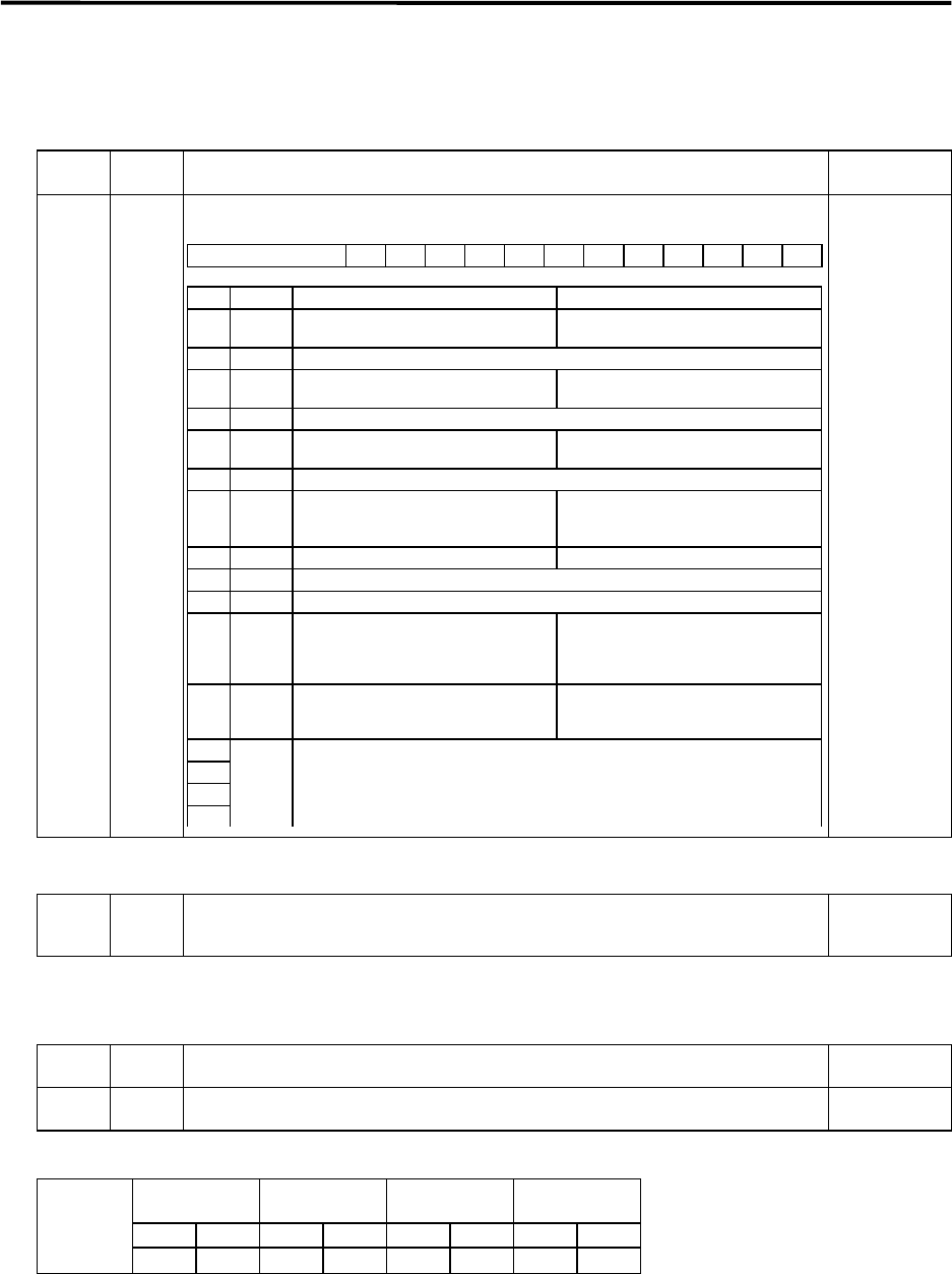
F E D C B A 9 8 7 6 5 4 3 2 1 0
spm drvall drvup mpt3 mp abs vmh vdir fdir seqh dfbx vdir2
bit Name Meaning when "0" is set Meaning when "1" is set
0 vdir2 Sub side (CN3 connector) feedback
forward polarity
Sub side (CN3 connector) feedback
reverse polarity
1 dfbx Set to "0".
2 seqh READY/servo ON time, normal mode READY/servo ON time, time reduction
mode
3 Set to "0".
4 fdir Main side (CN2 connector) feedback
forward polarity
Main side (CN2 connector) feedback
reverse polarity
5 vdir Set to "0".
6 vmh Normal processing mode High-speed processing mode
∗ For the linear system, set the
high-speed processing mode.
7 abs Incremental position detection Absolute position detection
8 mp Set to "0".
9 mpt3 Set to "0".
A drvup Combination with standard motor driver Set when using a combination with a
driver having a capacity one rank
above or below the standard motor
drive.
B drvall Normal setting Set when using a combination of driver
having a capacity different from the
standard motor driver.
C
D
E
F
spm Standard linear motor : 6
Special linear motor : 7
Refer to (5) List of motor types.
∗2 Set the resolution per magnetic pole
pitch in RNG1 and 2.
∗3 HR means the MDS-B-HR unit, and
is indicated when this unit is
connected between the scale.


