


Chapter 10 Adjustment
10–35
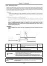
<Setting and adjustment methods>
1. Confirm that SHG control is being used.
2. SV032: TOF Thrust offset
Move the axis to be adjusted approx. F1000mm/mi with jog, etc., and check the load current
on the [I/F DIAGNOSIS screen, Servo Monitor]. If the current load during movement is
positive, check the max. value. If negative, check the min. value. Set the average value of the
+ and - directions.
3. SV045: TRUB Frictional force
Move the axis to be adjusted approx. F1000mm/min both directions with jog, etc., and check
the load current on the [I/F DIAGNOSIS screen, Servo Monitor]. Subtract the current load
value for – direction movement from the current load value for + direction movement, and
divide the result by 2. Set the absolute position of that value.
4. SV059: TCNV Estimated thrust gain
Set SV035: SSF4/clt(bitF) of the axis to be adjusted to 1.
Move the axis to be adjusted in both directions at the max. feedrate with jog, etc., until the
MPOF display on the [I/F DIAGNOSIS screen, Servo Monitor] stabilizes.
Set the MPOF value displayed on the [I/F DIAGNOSIS screen, Servo Monitor] screen.
Return SV035: SSF4/clt (bitF) to 0.
5. SV035: SSF4/cl2n (bitB)
If the acceleration/deceleration time constant is small and the current is limited, set 1.
6. SV060: TLMT Collision detection level (For method 1, G0 modal)
First, set 100. (If SV035: SSF4/clet is set to 1, the MPOF value will indicate the past 2-sec.
estimated disturbance thrust peak value, so this can be referred to for setting. Note that this
displayed value is averaged, so first set a value that is approx. double the displayed value.)
Carry out no-load operation at the max. rapid traverse speed. If an alarm occurs, increment
the setting unit by 20.
If an alarm does not occur, decrement the setting value by 10.
Set a value that is approx. 1.5-times the limit value where an alarm does not occur.
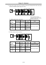
7. SV035: SSF4/clG1 (bit12-14)
Divide the max. cutting load by the SV060:TLMT setting value. (Round up the fraction). Set
this value.
(Example) When max. cutting load is 200% and SV060:TLMT setting value is 80%
200/80 = 2.5 The setting value is 3, so set 3xxx in SV035:SSF4.
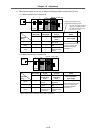
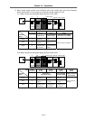
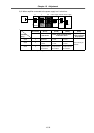
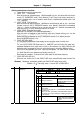
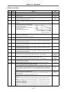
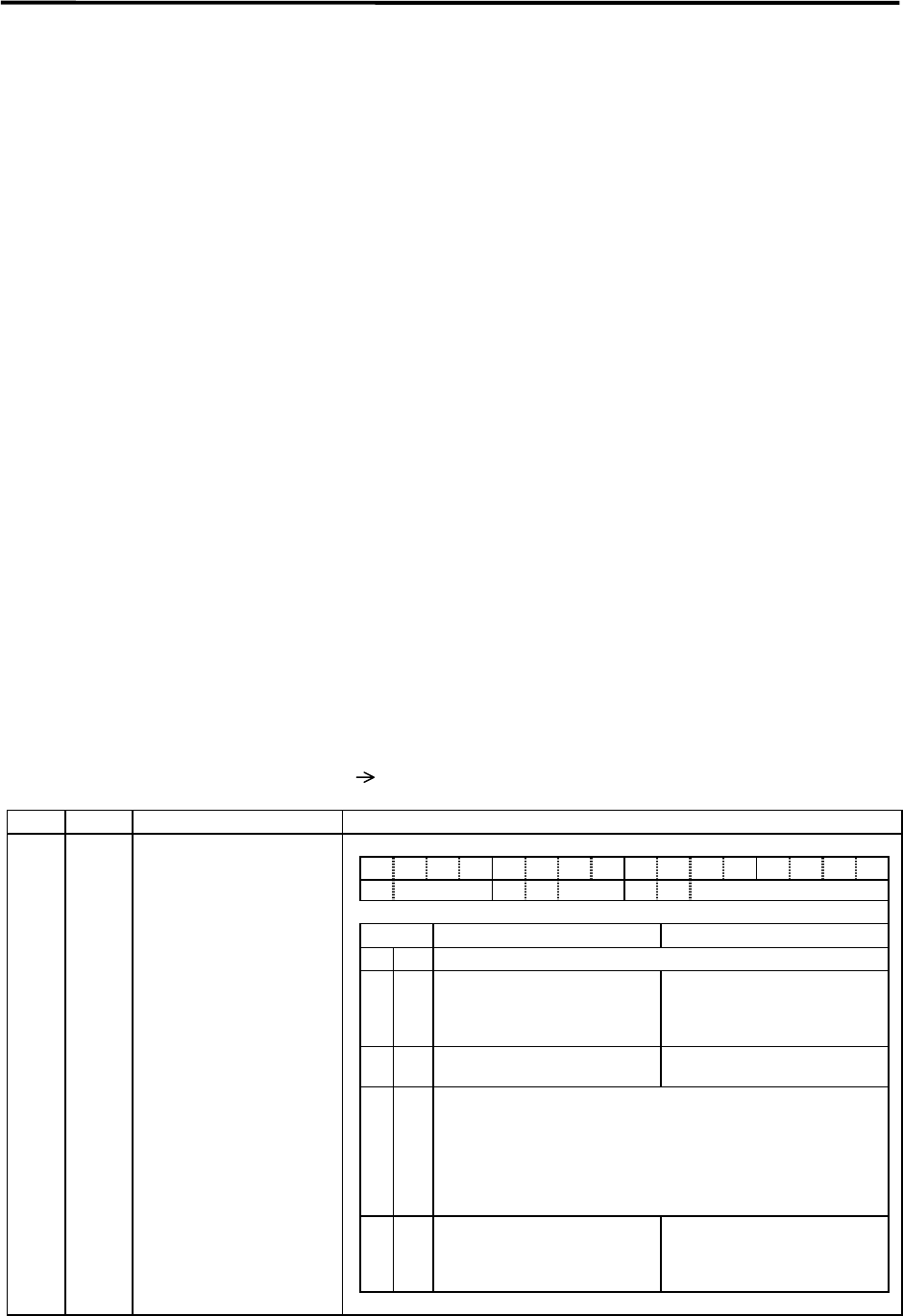
No. Abbrev. Parameter name Explanation
SV035 SSF4 The collision detection is set with the following parameters.
Special servo function
selection 4
15 14 13 12 11 10 9 8 7 6 5 4 3 2 1 0
clt clG1 cl2n clet cltq iup tdt
bit Meaning when "0" is set. Meaning when "1" is set.
8,9 cltq Set the deceleration torque for collision detection.
10 clet Setting for normal use
The past 2-sec. estimated
disturbance thrust peak value is
displayed at MPOF on the Servo
Monitor screen.
11 cl2n Setting for normal use
Collision detection method 2 is
invalidated.
12
to
14
clG1
Set the collision detection level for the collision detection method
1, G1 modal.
When 0 is set: The method 1, G1 modal collision detection will not
be carried out.
When 1 to 7 is set: The method 1, G0 modal collision detection
level will be set to a value obtained by multiplying (SV060: TLMT)
by the set value.
15 clt Setting for normal use
The guide value for the SV059:
TCNV setting value is displayed
at MPOF on the Servo Monitor
screen.