


Chapter 7 Installation
7–18
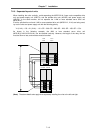
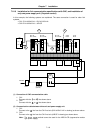
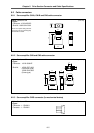
7-2-12 Connection with mechanical brakes
Mechanical brake (magnetic brake) contact connection terminal (EM1, EM2)
A brake terminal is provided on the MDS-B-V14L servo driver. When controlling mechanical brakes
using this terminal, connect the magnetic brake cable to the CN20 connector.
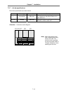
(1) Brake contact specifications
Item Specifications
Rated control capacity (resistance load) (AC) 8A 250V/(DC) 5A 30V
Max. tolerable contact power (resistance
load)
2000VA 150WA
Max. tolerable contact voltage/current (AC) 380V/8A
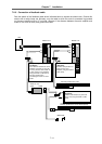
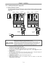
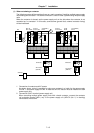
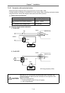
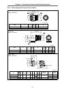
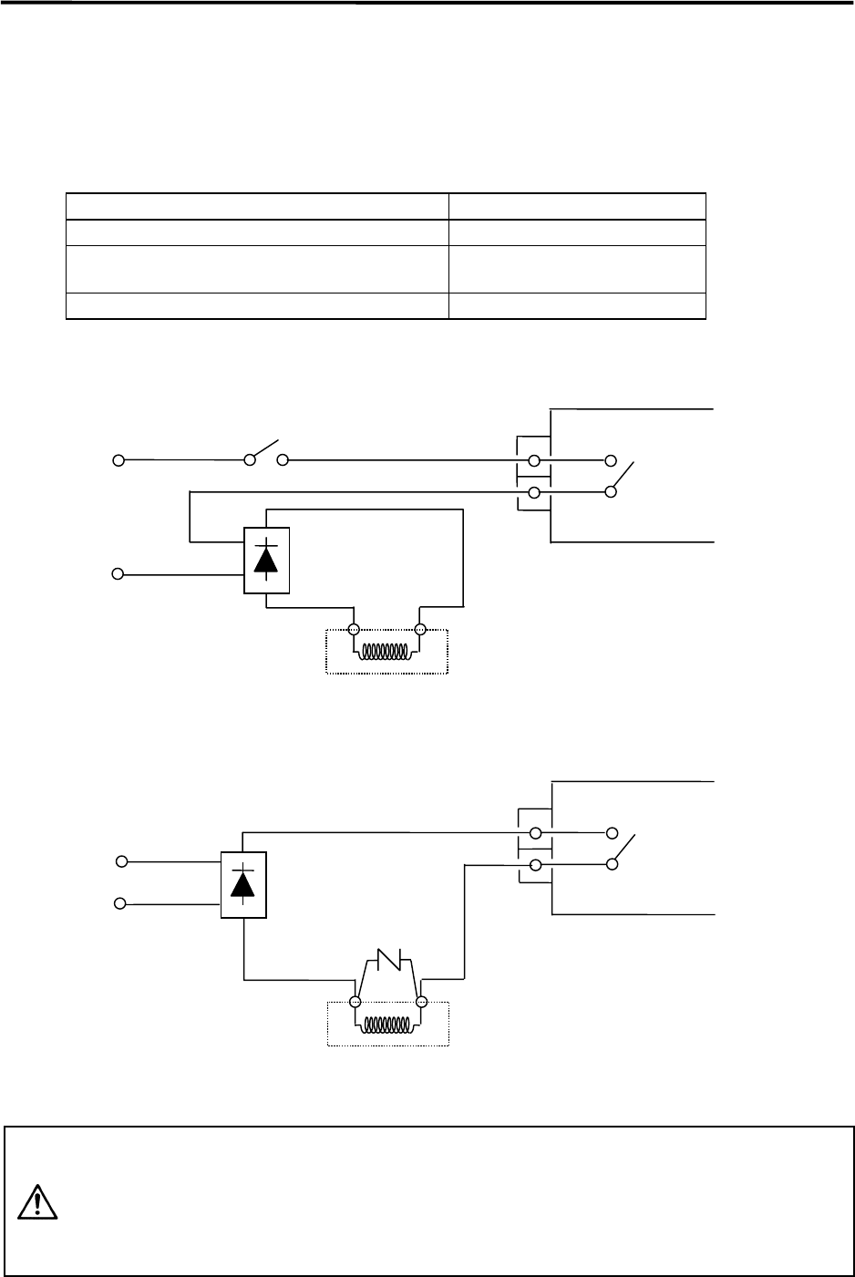
(2) Example of brake contact connection
1) For AC OFF
2) For DC OFF
VAR: Surge absorber (220V)
CAUTION
While the DC OFF is valid when the braking delay time is a problem, the
contact’s DC shut off capacity and the occurrence of error signals for CNC
must be confirmed.
Observe the following points.
1. Provide sufficient contact DC shut off capacity.
2. Use a surge absorber.
28VAC
SW
Rectifier
CN20
1
MDS-B-V14L
3
Brake excitation
EM2
Brake excitation
28VAC
Rectifier
CN20
1
MDS-B-V14L
3
EM1
EM2
RA1
VAR
EM1
RA1