


Chapter 7 Installation
7–8
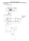
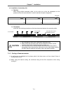
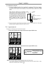
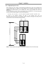
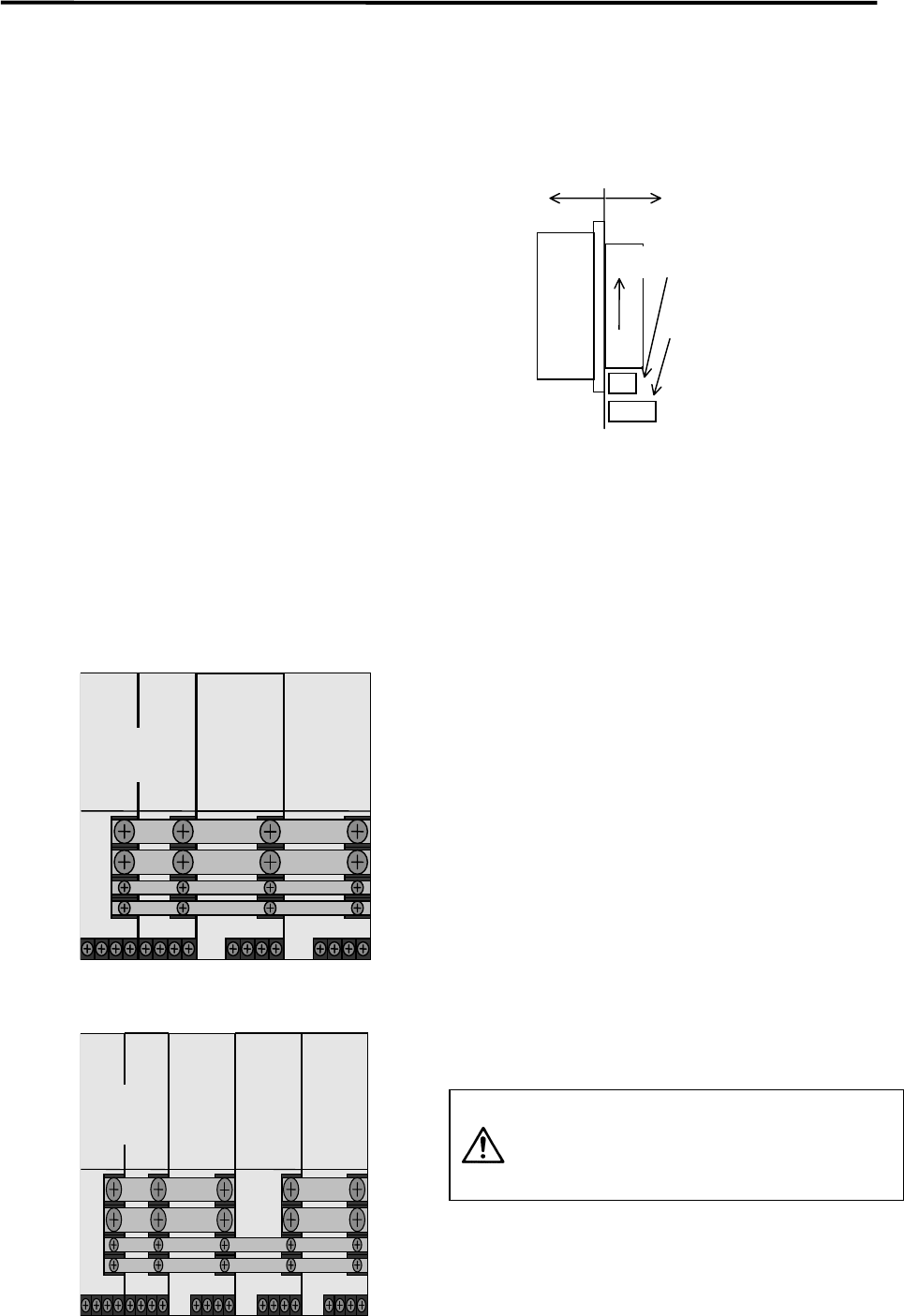
(5) Installing the cooling fan
1) Each unit (excluding type without fins) is provided with a cooling fan (FAN1 below). However,
to maintain operation when the fan stops due to deterioration of the fan's ambient
environment, and to improve the serviceability, the user should install an additional fan (FAN2
below).
When using the sealed type unit installation
method and the panel structure could easily
allow cutting oil or dust to enter from the unit's
fin and fan section (in other words, when the
fan could stop due to the ambient environment),
the user should add a fan at the position shown
as FAN2 on the right. Carry out forced cooling
with a velocity of 2m/s or more. The
serviceability must also be considered in this
case.
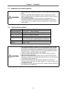
2) Due to the structure, heat will easily accumulate in each unit. Thus, install a fan in the power
distribution panel to agitate the heat at the top of the unit.
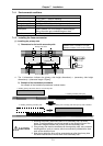
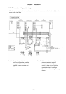
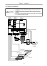
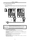
7-2-4 Layout of each unit
Principally, the following layout is used as the standard.
1) When total of spindle motor output and servomotor output is 38kW or less
Servo
drive unit
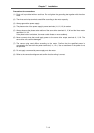
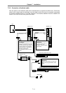
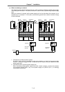
2) When total of spindle motor output and servomotor output is 38kW or more
(Note) As a principle, keep the clearance between each unit at 3cm or less.
If the clearance between the spindle drive unit and servo drive unit must be 3cm or more,
observe the conditions given in section 7-2-8.
CAUTION
Always connect the L+ and
L– link bars of power supply
No. 1 and No. 2
independently.
Inside
panel
Outside
panel
Wind
direction
FAN1
(Mounted as a standard on
unit)
FAN2
(Additionally installed by user)
... Install a finger cover for
safety purposes.
L+
L–
L1+
L1–
Power
supply
unit
Spindle
drive unit
L+
L–
L1+
L1–
Power
supply
unit No.1
Spindle
drive
unit
Servo
drive
unit
Power
supply
unit No.2