


Chapter 10 Adjustment
10–28
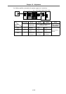
(3) Adjustment procedures
• Set the drop prevention function parameters in the vertical axis servo parameters SV048, 055
and 056.
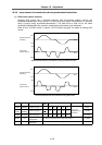
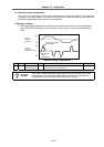
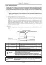
1) Set the vertical axis parameter SV048 (vertical axis drop prevention time) to 50, 100, ...
while carrying out emergency stop, and set the value for which the drop amount is the
minimum on the CNC screen. (There will be several um due to the brake play.)
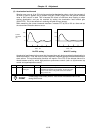
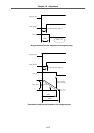
2) Set SV056 (deceleration control during emergency stop time constant). Normally, set the
same value as the rapid traverse time constant.
3) Set SV055 (emergency stop max. delay time). Normally, set the same value as SV048. To
turn READY OFF after deceleration stop, set the same value as SV056. Note that this is
valid when SV056 (deceleration control during emergency stop time constant) is larger than
SV048 (vertical axis drop prevention time).
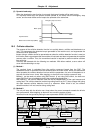
• If the axis controlling the power supply (axis to which CN4 cable is connected) that supplies the
power to the target vertical axis is another servo axis, set the servo parameters SV048, 055 and
056 for that axis to the same values as the vertical axis. (If there are multiple vertical axes, set
the max. value.)
• When the 2-axis driver is a vertical axis or an axis controlling the power supply, set servo
parameters SV048, 055 and 056 for both the L and M axes.
• If the axis controlling the power supply is the main axis, confirm that a compatible spindle driver
software version is being used, and set the spindle parameter SP033 bitF to 1.
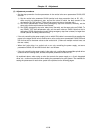
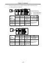
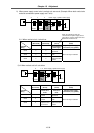
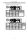
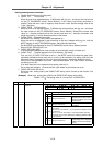
As explained above, when using an axis that controls the power supply or a 2-axis integrated
driver, etc., caution must be taken when setting the parameters for each system. The methods for
setting the parameters for each drive system are explained on the following pages.