


Chapter 10 Adjustment
10–41
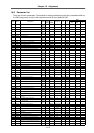
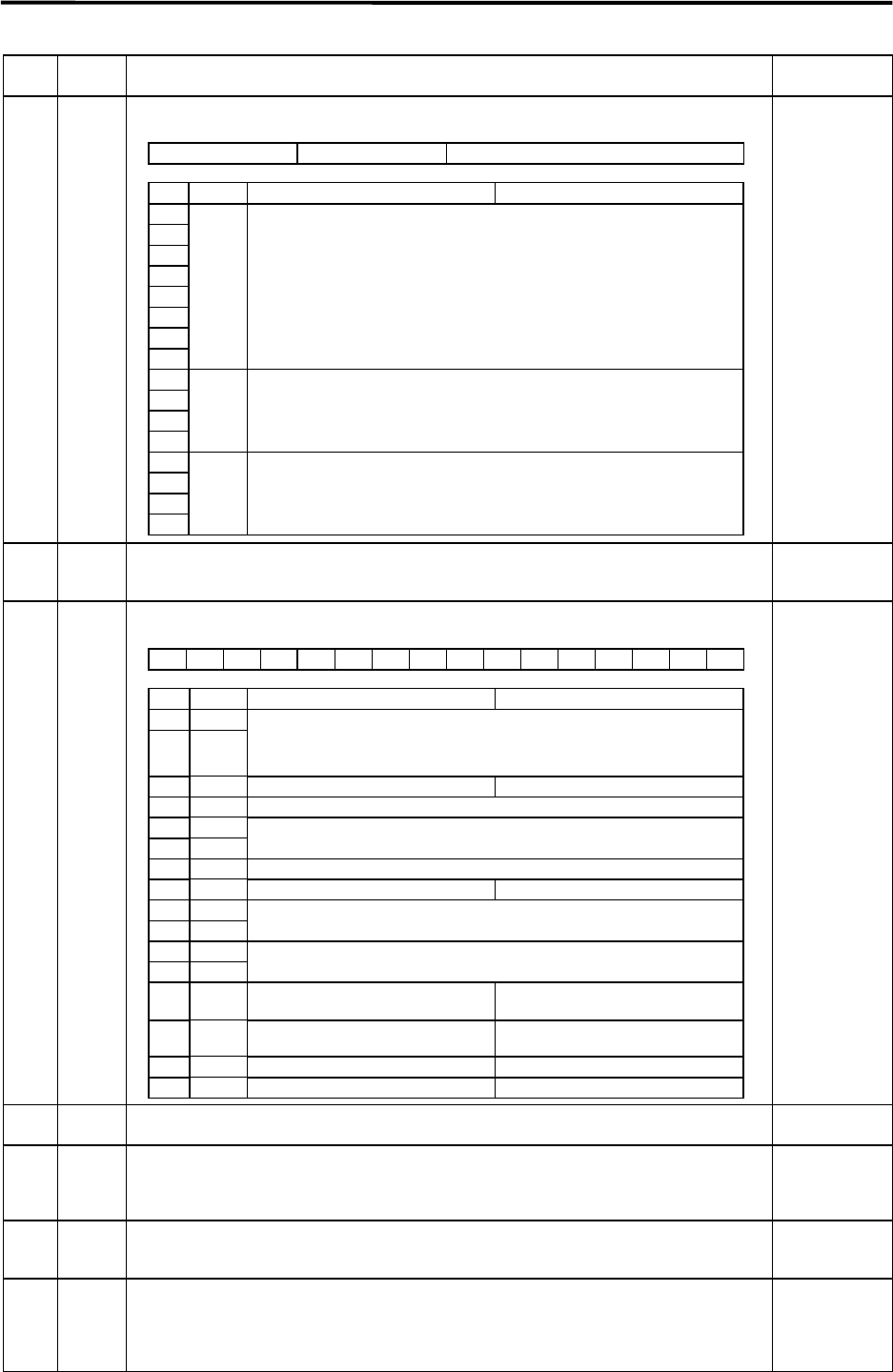
Name Abbrev. Details
Setting range
(unit)
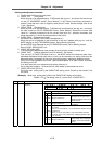
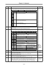
SV025 MTYP
Motor/detector type
HEX setting
SV026 OD2 Set the excessive error detection width for servo OFF. Normally, the same value as
SV023:OD1 is set.
When 0 is set, the excessive error will not be detected at servo OFF.
0 to 32767
(mm)
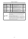
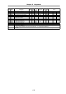
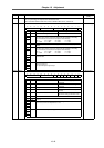
SV027 SSF1
Special servo function selection 1
HEX setting
∗
Note 1
When afse
(bitC) is set to
"1", also set
afrg (bitD) to
"1".
SV028 MSFT Set the pole shift amount. –30000 to 30000
(µm)
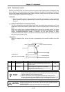
SV029 VCS If the noise is bothersome during high-speeds, such as during rapid traverse, set the speed
loop gain's drop start motor speed.
The speed loop gain drop target speed loop gain is set in SV006: VGN2.
Set to 0 when not using this function.
0 to 9999
(mm/s)
SV030 IVC • Voltage non-sensitive band compensation: The low-order 8 digits are used.
• Current bias: The high-order 8 digits are used. (Icx)
This is used in combination with the SV040 and SV045 high-order 8 digits.
–32768 to 32767
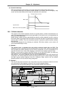
SV031 OVS1 Set this if overshooting occurs during deceleration stop with control using the submicron
control or system using CN3. The overshooting will be improved as the value is increased.
Normally, set this as approx. 2 to 10 (%) (percentage in respect to stall rated current).
(Increment the value in 2% increments and find the value where overshooting does not occur.)
This is valid only when overshoot compensation (SV027: SSF1/ovs1, ovs2) is selected.
–1 to 100
(Stall rated
current %)
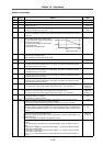
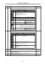
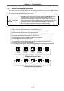
F E D C B A 9 8 7 6 5 4 3 2 1 0
pen ent mtyp
bit Name Meaning when "0" is set Meaning when "1" is set
0
1
2
3
4
5
6
7
mtyp Set the motor type.
(Refer to 7-201 (6) List of motor types.)
8
9
A
B
ent Set the speed detector type.
(Refer to 9-2-1 (6) List of detector types.)
C
D
E
F
Pen Set the position detector type.
(Refer to 9-2-1 (6) List of detector types.)
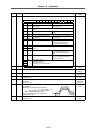
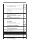
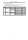
F E D C B A 9 8 7 6 5 4 3 2 1 0
aflt zrn2 afrg afse ovs2 ovs1 lmc2 lmc1 omr vfct2 vfct1 upc vcnt2 vcnt1
bit Name Meaning when "0" is set Meaning when "1" is set
0 vcnt1
1 vcnt2
00: Delay compensation changeover
invalid
01: Delay compensation changeover
type 1
10: Delay compensation changeover
type 2
11: Spare
2 upc Start torque compensation invalid Start torque compensation valid
3 Set to "0".
4 vfct1
5 vfct2
00: Jitter compensation invalid
01: Jitter compensation 1 pulse
10: Jitter compensation 2 pulse
11: Jitter compensation 3 pulse
6 Set to "0".
7 omr OMR control invalid OMR control valid
8 lmc1
9 lmc2
00: Lost motion compensation valid
01: Lost motion compensation type 1
10: Lost motion compensation type 2
11: Spare
A ovs1
B ovs2
00: Overshoot compensation invalid
01: Overshoot compensation type 1
10: Overshoot compensation type 2
11: Overshoot compensation type 3
C afse Setting for normal use Adaptive filter sensitivity increase
Note 1
D afrg Setting for normal use Set this when the adaptive filter is
effective in the speed band.
E zrn2 Reference point return type 1 Reference point return type 2
F aflt Adaptive filter invalid Adaptive filter valid