


Chapter 10 Adjustment
10–7
10-3 Characteristics improvement
10-3-1 Optimal adjustment of cycle time
The following items must be adjusted to adjust the cycle time. Refer to the Instruction Manuals
provided with each CNC for the acceleration/deceleration pattern.
1) Rapid traverse rate (rapid) : This will affect the maximum speed during positioning.
2) Clamp speed (clamp) : This will affect the maximum speed during cutting.
3) Acceleration/deceleration time : Set the time to reach the feedrate.
constant (G0t*, G1t*)
4) In-position width (SV024) : This will affect each block's movement command end time.
5) Position loop gain (SV003) : This will affect each block's movement command settling time.
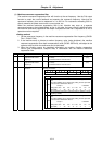
(1) Adjusting the rapid traverse rate
To adjust the rapid traverse, the CNC axis specification parameter rapid traverse rate (rapid) and
acceleration/deceleration time constant (G0t*) are adjusted. The rapid traverse rate is set so that
the motor speed matches the machine specifications in the range below the maximum speed in
the motor specifications. For the acceleration/deceleration time constants, carry out rapid traverse
reciprocation operation, and set so that the maximum current command value at
acceleration/deceleration is within the range shown below.
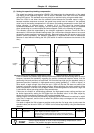
When adjusting, watch the current FB waveform during acceleration/deceleration, and adjust so
that the thrust is within the specified range. Be careful, as insufficient thrust can easily occur when
the driver input voltage is low (170 to 190V), and an excessive error can easily occur during
acceleration/deceleration.
(2) Adjusting the cutting rate
To adjust the cutting rate, the CNC axis specification parameter clamp speed (clamp) and
acceleration/deceleration time constant (G1t*) are adjusted. The in-position width at this time
must be set to the same value as actual cutting.
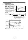
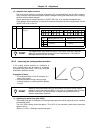
• Determining the clamp rate and adjusting the acceleration/deceleration time constant
(Features) The maximum cutting rate (clamp speed) can be determined freely.
(Adjustment) Carry out cutting feed reciprocation operation with no dwell at the maximum
cutting rate and adjust the acceleration/deceleration time constant so that the
maximum current command value during acceleration/deceleration is within the
range shown below.
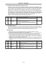
• Setting the step acceleration/deceleration and adjusting the clamp speed
(Features) The acceleration/deceleration time constant is determined with the position loop
in the servo, so the acceleration/deceleration F∆T can be reduced.
(Adjustment) Set 1 (step) for the acceleration/deceleration time constant and carry out cutting
feed reciprocation operation with no dwell. Adjust the cutting feed rate so that
the maximum current command value during acceleration/deceleration is within
the range shown below, and then set the value in the clamp speed.
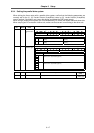
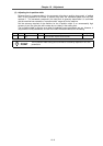
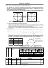
Self-cooling Oil-cooling
Motor type
Max. current
command value
Motor type
Max. current
command value
LM-NP2S-05M 600 to 680% LM-NP2S-05M 270 to 310%
LM-NP2M-10M 590 to 670% LM-NP2M-10M 275 to 310%
LM-NP2L-15M 565 to 640% LM-NP2L-15M 270 to 306%
LM-NP4S-10M 590 to 670% LM-NP4S-10M 275 to 312%
LM-NP4M-20M 550 to 620% LM-NP4M-20M 262 to 300%
LM-NP4L-30M 570 to 650% LM-NP4L-30M 272 to 310%
LM-NP4G-40M 560 to 640% LM-NP4G-40M 271 to 307%