


Chapter 10 Adjustment
10–42
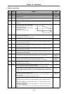
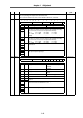
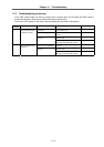
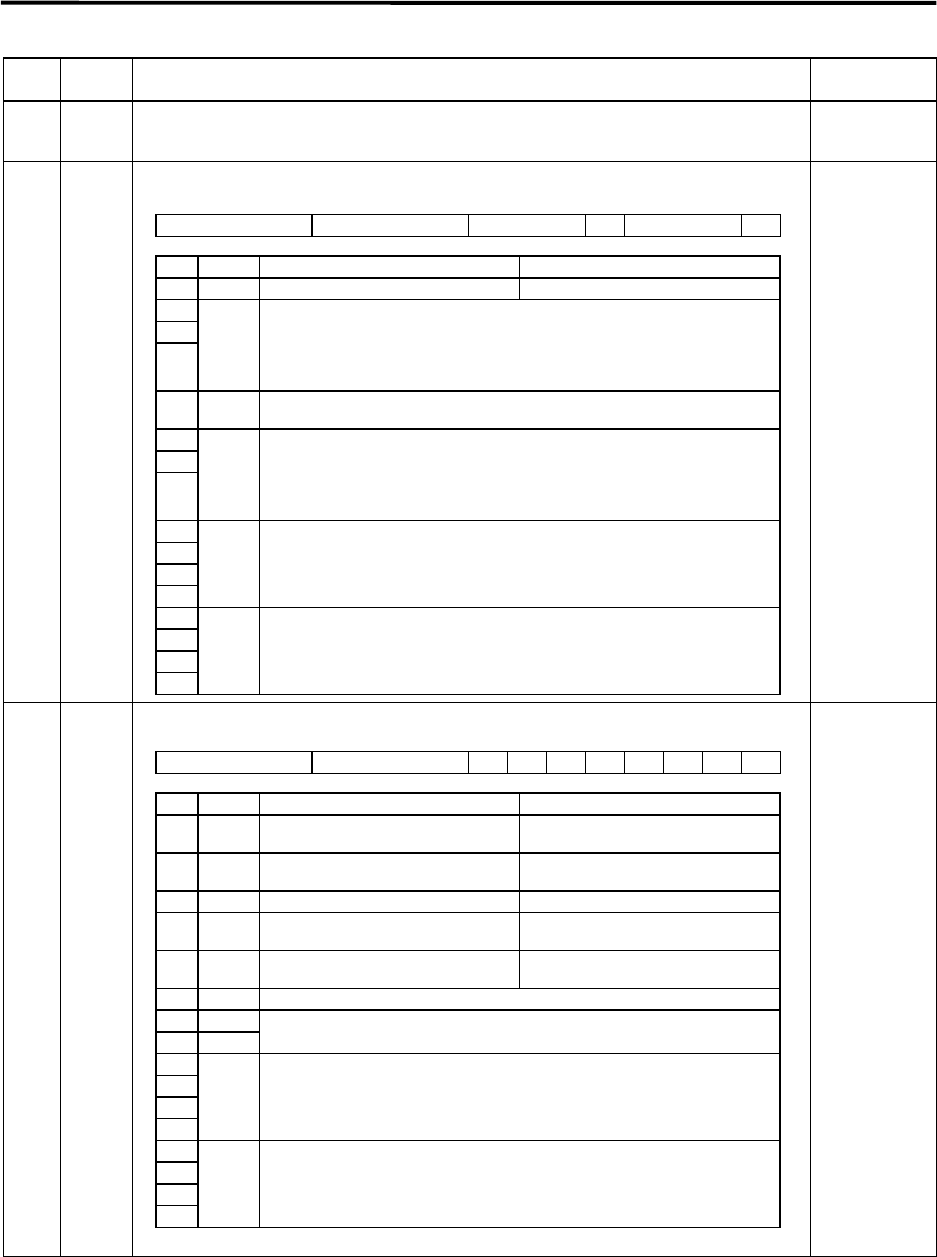
Name Abbrev. Details
Setting range
(unit)
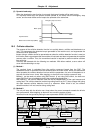
SV032 TOF Set the unbalance thrust amount of an axis having an unbalanced thrust, such as a vertical
axis, as a percentage in respect to the stall rated current.
This is used when SV027: SSF1/lmc1, lmc2 or SV027: SSF1/vcnt1, vcnt2 is set.
–100 to 100
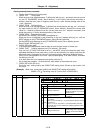
SV033 SSF2
Special servo function selection 2
HEX setting
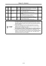
SV034 SSF3
Special servo function selection
3
HEX setting
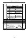
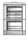
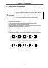
F E D C B A 9 8 7 6 5 4 3 2 1 0
dos dis nfd2 nf3 nfd1 zck
bit Name Meaning when "0" is set Meaning when "1" is set
0 zck Z phase check valid (part of alarm 42) Z phase check invalid
1
2
3
nfd1 Adjust the damping mount of the 1st machine resonance suppression filter.
The effect of the machine resonance suppression filter will drop as the setting
value is increased, and the effect on the speed control will drop.
000: –∞ 010: –12dB 100: –6dB 110: –3dB
001: –18dB 011: –9dB 101: –4dB 111: –1dB
4 nf3
Validate the 3rd machine resonance suppression filter. (Center frequency fixed to
1125Hz)
5
6
7
nfd2 Adjust the damping mount of the 2nd machine resonance suppression filter.
The effect of the machine resonance suppression filter will drop as the setting
value is increased, and the effect on the speed control will drop.
000: –∞ 010: –12dB 100: –6dB 110: –3dB
001: –18dB 011: –9dB 101: –4dB 111: –1dB
8
9
A
B
dis Digital signal input selection
Set this to 0000.
C
D
E
F
dos Digital signal output selection
0000: For normal use
0001: Specified speed signal output
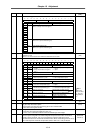
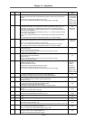
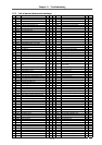
F E D C B A 9 8 7 6 5 4 3 2 1 0
ovsn linN toff os2 dcd test mohn has2
(has1)
bit Name Meaning when "0" is set Meaning when "1" is set
0 has1 Setting for normal use (HAS control 1 valid, high-speed
compatible)
1 has2 Setting for normal use HAS control 2 valid, overshooting
compatible
2 mohn Setting for normal use Ignore MDS-B-HR motor thermal error
3 test Setting for normal use Default test (Errors are sensitively
detected)
4 dcd Setting for normal use DC excitation mode
Use this for setting up the linear motor.
5 Set to "0".
6 os2
7 toff
Not used for linear motor.
Set to "0".
8
9
A
B
linN Set the No. of axes connected in parallel when using the linear motor.
When 0 is set, the No. is interpreted as 1 axis.
C
D
E
F
ovsn Set the overshoot compensation type 3 non-sensitive band.