


Chapter 11 Troubleshooting
11–8
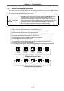
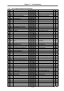
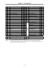
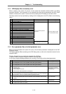
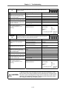
11-5 LED display Nos. at memory error
When a memory error (alarm 12) occurs, in most cases the connection with the CNC is not being
executed. Normally, if the connection is not executed even when the connected with the CNC, check
whether a memory error (alarm 12) has occurred by reading the LED display on the servo driver.
The faulty section can be pinpointed by reading the No. displayed on the LED. (Refer to the following
table.)
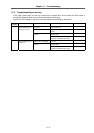
No. Details Time of occurrence Alarm display
– Power PCB ID error When CNC power is turned ON Normal alarm display
01 LSI internal RAM error 1
02 LSI internal RAM error 2
03 LSI transmission buffer error
04 LSI reception buffer error
05 External SRAM error
11 LSI timing status error
21 LSI encoder I/F counter error L axis MAIN
22 LSI encoder I/F counter error L axis SUB
23 LSI encoder I/F counter error L axis MAIN
24 LSI encoder I/F counter error L axis SUB
31 External FLASH boot code error 1
32 External FLASH check sum error 1
33 External FLASH boot code error 2
34 External FLASH check sum error 2
41 CPU internal RAM error 1
When servo driver power is
turned ON
42 CPU internal RAM error 2
51 Driver model error
When CNC power is turned ON
12 and No. flicker on LED
(Not connected with CNC)
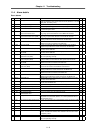
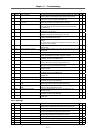
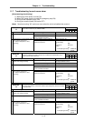
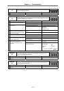
11-6 Error parameter Nos. at initial parameter error
When an initial parameter error (alarm 37) occurs, the erroneous parameter is displayed on the CNC
Diagnosis screen.
The display method differs according to the CNC being used, so refer to the instruction manual for the
respective CNC.
The No. displayed here is normally the parameter No. (SV00xx).
In addition, there is a special 3-digit No. (Refer to following table.)
In this case, multiple related parameters are occurring, so correctly set the related parameters.
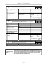
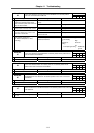
No. Details Related parameter
69 The max. rapid traverse speed setting value set in the CNC is incorrect.
This normally will not occur, and is a problem in the CNC system software.
CNC axis parameter rapid
71 The max. cutting speed setting value set in the CNC is incorrect.
This normally will not occur, and is a problem in the CNC system software.
CNC axis parameter clamp
101 The constants used with the following functions are overflowing.
Electronic gears
Position loop gain
Speed feedback conversion
Confirm that each related parameter is correctly set.
SV001:PC1,SV002:PC2
SV003:PGN1,SV018:PIT
SV019:RNG1,SV020:RNG2
SV049:PGN1sp
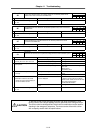
102 Turn the absolute position detection parameter OFF.
The connected detector is an incremental specification detector, so to carry out absolute
position detection, connect an absolute position specification detector.
SV017:SPEC,SV025:MTYP
103 There is no servo option.
The closed loop (including ball screw end detection) and dual feedback control function
are options.
SV025:MTYP/pen
SV017:SPEC/dfbx
104 There is no servo option.
The SHG control function is an option.
SV057:SHGC
SV058:SHGCsp
105 There is no servo option.
The adaptive filter function is an option.
SV027:SSF1/aflt