


Chapter 10 Adjustment
10–39
Details of parameters
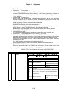
No.
Abbrev.
Details
Setting range
(Unit)
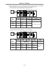
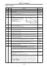
SV001 PC1 Set 1 for the linear motor system. 1 to 32767
SV002 PC2 Set 1 for the linear motor system. 1 to 32767
SV003 PGN1 Set the position loop gain in increments of 1.
Normally, 47 is set.
1 to 200
(rad/s)
SV004 PGN2 When carrying out SHG control, set together with SV057: SHGC.
Normally, 0 is set when not using 125.
0 to 999
(rad/s)
SV005 VGN1 Set the speed loop gain.
150 is set as a standard. If increased, the response will increase but the vibration and noise
will increase.
1 to 999
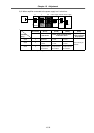
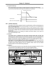
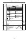
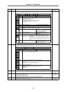
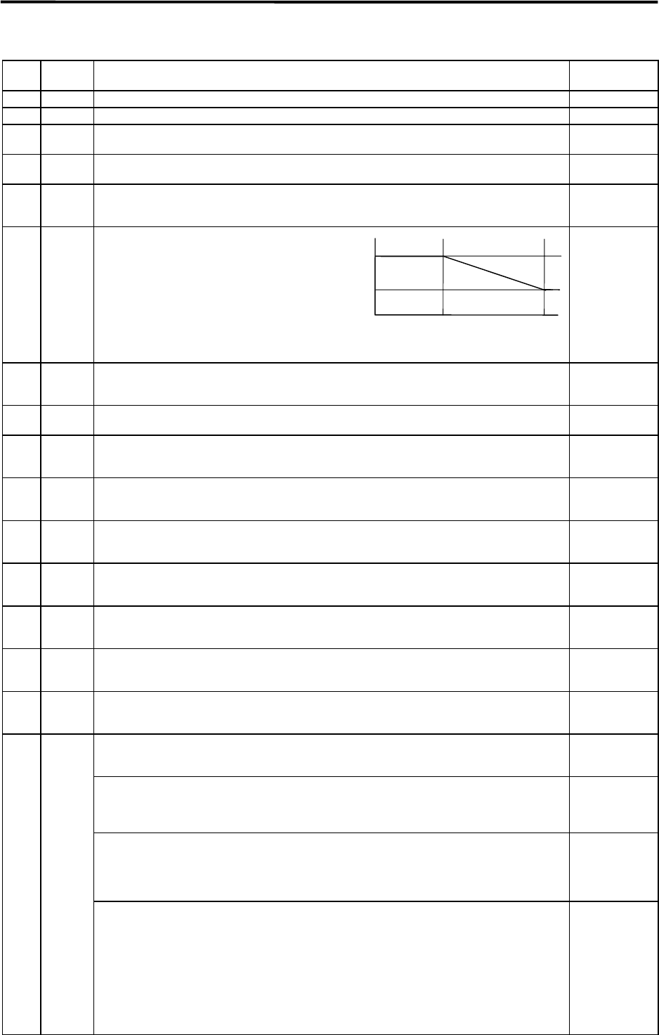
SV006 VGN2 If the noise is bothersome at high speeds,
such as during rapid traverse, set the speed
loop gain (smaller than VGN1) for high speeds
(1.2-times the rated speed).
The speed to start dropping the speed gain is
set with SV029:VCS.
Set 0 when not using this function.
–1000 to 1000
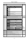
SV007 VIL Set this when a limit cycle occurs, of if overshooting occurs during positioning.
Set 0 when not using this function.
Related parameters: SV027:SSF1/vcnt1, vcnt2
0 to 32767
SV008 VIA Set the speed loop advance compensation. 1 to 9999
(0.0687rad/s)
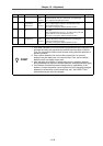
SV009 IQA Set the current loop internal compensation.
The setting value is fixed according to the motor being used. (Refer to section 9-2-4 List of
standard parameters for each motor.)
1 to 20480
SV010 IDA Set the current loop internal compensation.
The setting value is fixed according to the motor being used. (Refer to section 9-2-4 List of
standard parameters for each motor.)
1 to 20480
SV011 IGQ Set the current loop internal compensation.
The setting value is fixed according to the motor being used. (Refer to section 9-2-4 List of
standard parameters for each motor.)
1 to 4096
SV012 IDG Set the current loop internal compensation.
The setting value is fixed according to the motor being used. (Refer to section 9-2-4 List of
standard parameters for each motor.)
1 to 4096
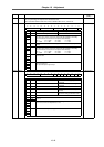
SV013 ILMT Set the current limit value as a percentage (%) in respect to the stall rated current.
To use to the driver's max. thrust, set 800. (Limit value in both + and – directions.)
0 to 999
(Stall rated
current %)
SV014 ILMTsp Set the current limit value for special operations (absolute position default setting, stopper
operation, etc.) as a percentage (%) in respect to the stall rated current.
To use to the driver's max. thrust, set 800. (Limit value in both + and – directions.)
0 to 999
(Stall rated
current %)
SV015 FFC Set this when the overshooting amount during feed forward control, or the relative error during
synchronous control, etc., is large.
Set to 0 when not using this function.
0 to 999
(%)
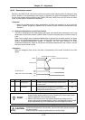
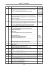
Set this parameter if the protrusion (caused by non-sensitive band from friction, torsion,
backlash, etc.) is large when the arc quadrant is changed.
This is valid only when lost motion compensation (SV027: lmc1, lmc2) are selected.
–1 to 200
Type 1
SV027:SSF1/lmc1=1/lmc2=0
Protrusions during low-speed interpolation can be eliminated with this type of compensation.
The compensation gain will be 0 when 0 is set. 100% compensation will be carried out when
100 is set.
0 to 200
(%)
Type 2
SV027:SSF1/lmc1=0/lmc2=1
This type is the standard for the MDS Series.
Use this type during high-speed high-accuracy interpolation if sufficient compensation is not
possible with type 1.
Set as a percentage (%) in respect to the stall rated current.
0 to 100
(Stall rated
current %)
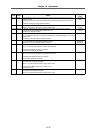
SV016 LMC1
To change the compensation gain (type 1) or compensation amount (type 2) according to the
direction.
To set a different value according to the command direction, set this in addition to SV041:
LMC2.
Set the value for changing the command speed from the – to + direction (during command
direction CW) in SV016:LMC1.
Set the value for changing the command speed from the + to – direction (during command
direction CW) in SV041:LMC2.
When –1 is set, compensation will not be carried out when the command speed direction
changes.
(Motor rated speed × 1.2)
VLM 0
VGN2
VGN1
VCS