


Chapter 10 Adjustment
10–15
<Adjustment method>
First confirm whether the axis to be compensated is an unbalance axis (vertical axis, slant axis). If
it is an unbalance axis, carry out the adjustment after performing step "(2) Unbalance thrust
compensation".
Next, measure the frictional torque. Carry out reciprocation operation (approx. F1000) with the
axis to be compensated and measure the load current % when fed at a constant speed on the
CNC servo monitor screen. The frictional force of the machine at this time is expressed with the
following expression.
Frictional force % =
(+ feed load current %) – (– feed load current %)
2
The standard setting value for the lost motion compensation 1 (LMC1) is double the frictional
torque above.
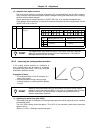
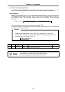
Assume that the load current % was 25% in the + direction and –15% in the –
direction when JOG feed was carried out at approx. F1000. The frictional force is as
shown below, so 20% × 2 = 40% is set for LMC1. (LMC2 is left set at 0.) With this
setting, 40% compensation will be carried out when the command reverses from the +
direction to the - direction, and when the command reverses from the – direction to the
+ direction.
25 – (–15)
2
= 20%
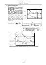
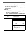
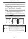
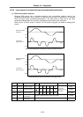
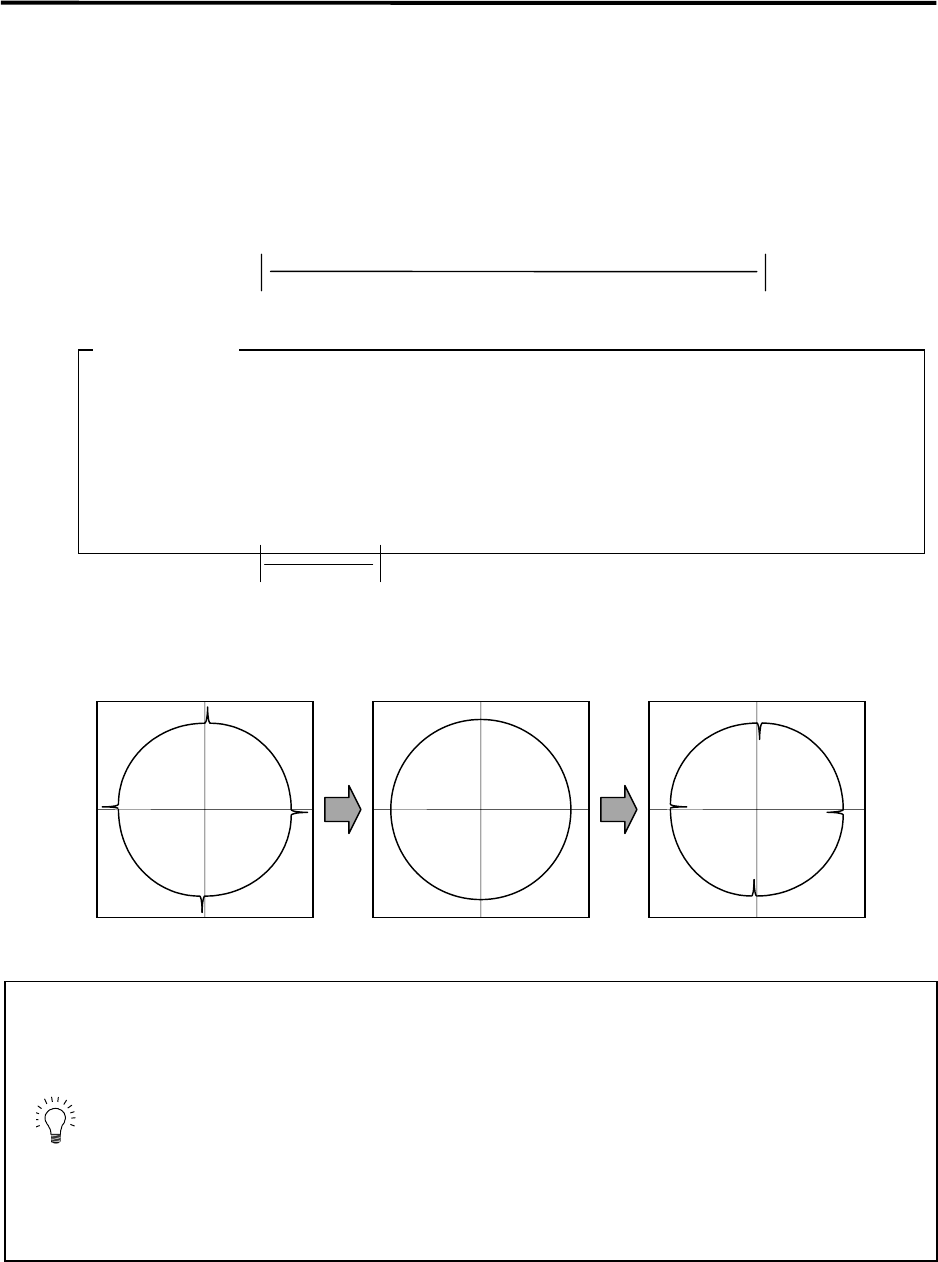
For the final adjustment, measure the CNC sampling measurement (DBB measurement) or while
carrying out actual cutting. If the compensation amount is insufficient, increase LMC1 or LMC2 by
5% at a time. Note that if the setting is too high, biting may occur.
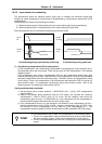
Compensation 0 Optimum Too high
POINT
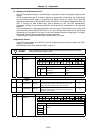
1. When either parameter SV016: LMC1 or SV041: LMC2 is set to 0, the same
amount of compensation is carried out in both the positive and negative
direction with the setting value of the other parameter (the parameter not set
to 0).
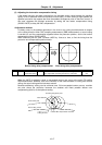
2. To compensate in only one direction, set -1 in the parameter (LMC1 or
LMC2) for the direction in which compensation is prohibited.
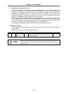
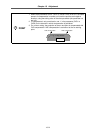
3. The value set based on the frictional force is the standard value for LMC
compensation. The optimum compensation amount changes with the
cutting conditions (cutting speed, cutting radius, blade type, workpiece
material, etc.). Be sure to ultimately make test cuts matching the target
cutting and determine the compensation amount.
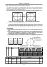
(Example)