


Chapter 2 Drive System Configuration
2–5
2-3 Linear motor drive system
CAUTION
1. With the linear servo system, the linear motor is assembled into the
machine, and the position detector (linear scale) is also installed when the
machine is assembled. Thus, it is not possible to know the motor pole
position beforehand as information in the CNC unit. At the first machine
startup, basically, the servo loop cannot be applied, so take special care
when starting up a machine having an unbalanced axis such as a gravity
axis.
CAUTION
2. The linear servomotor basically does not have any devices such as the
magnetic brakes installed. Thus, when using this for an axis onto which an
unbalance force is applied, such as a gravity axis, install a stopping device
on the machine side to secure safety.
CAUTION
3. Use the linear servomotor and servo amplifier with the designated
combination.
For an unbalanced axis, such as a gravity axis, basically balance it with a
device such as a counterbalance. With the linear motor, the continuous
thrust is lower than the rotary motor, so if the axis is unbalanced the motor's
heating amount will increase. If an error should occur, the axis will drop
naturally. This is hazardous as the dropping distance and dropping speed
are large.
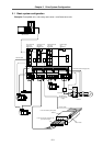
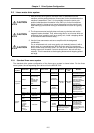
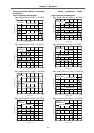
2-3-1 Standard linear servo system
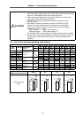
The standard drive system configuration of the linear servo system is shown below. For the linear
servo system, the corresponding servo drive unit is the MDS-B-V14L.
Detection
system
Resolution Max. speed Servo driver Linear scale Scale I/F
Pole
detection
unit
Remarks
0.04µm 120m/min
LS186
(Heidenhain)
Standard
incremental system
0.08µm
480m/min
Note currently
this is
120m/min due
to restrictions
by the linear
motor.
LIDA181
(Heidenhain)
High-speed
operation is possible.
However, as the
scale is an open
type, there are limits
to the working
environment.
0.008µm 48m/min
MDS-B-V14L-
LIF181
(Heidenhain)
MDS-B-H
R11M
MDS-B-M
D-600
This has a high
resolution so the
controllability is
increased. The max.
speed is limited.
(Open type scale)
Incre-ment
al system
With the above three types, an analog voltage output type scale can also be used.
0.1µm 120m/min
LC191M
(Heidenhain)
— —
0.5m 110m/min
AT342
(Mitsutoyo)
— —
Standard absolute
system.
Absolute
system
Absolute
position
0.5µm
Position/
speed
resolution for
control
0.04µm
110m/min
MDS-B-V14L-
AT342
special
(Mitsutoyo)
MDS-B-H
R-21M
—
This has a high
resolution so the
controllability is
increased. (The
control position and
speed resolution are
increased.)
MDS-B-HR-21 can be
used when detecting the
motor thermal signal
with the CNC.