


i
Contents
Chapter 1 Outline
1-1 Outline ..................................................................................................................... 1-2
1-2 Features................................................................................................................... 1-2
Chapter 2 Drive System Configuration
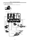
2-1 Basic system configuration................................................................................... 2-3
2-2 List of units and corresponding linear motors.................................................... 2-4
2-3 Linear motor drive system..................................................................................... 2-5
2-3-1 Standard linear servo system ......................................................................... 2-5
2-3-2 Configuration of parallel drive system............................................................. 2-8
Chapter 3 Selection
3-1 Selecting the linear servomotor............................................................................ 3-2
3-1-1 Max. feedrate.................................................................................................. 3-2
3-1-2 Max. thrust ...................................................................................................... 3-2
3-1-3 Continuous thrust............................................................................................ 3-4
3-2 Selecting the power supply unit ........................................................................... 3-6
3-3 Selecting the power supply capacity, wire size, AC reactor,
contactor and NFB ................................................................................................. 3-6
Chapter 4 Linear Servomotor Specifications
4-1 Type configuration ................................................................................................. 4-2
4-2 List of specifications.............................................................................................. 4-3
4-3 Speed – torque characteristics drawing (At input voltage 200VAC) ................. 4-4
4-4 Dynamic brake characteristics.............................................................................. 4-5
4-5 Outline dimensions ................................................................................................ 4-6
4-6 Explanation of connectors .................................................................................... 4-9
Chapter 5 Servo Drive Specifications
5-1 Type configuration ................................................................................................. 5-2
5-2 List of specifications.............................................................................................. 5-3
5-3 Overload protection specifications ...................................................................... 5-4
5-4 Outline dimensions ................................................................................................ 5-6
5-5 Explanation of connectors and terminal blocks.................................................. 5-8
5-6 Dynamic brake unit ................................................................................................ 5-9
5-6-1 Connection of dynamic brake unit .................................................................. 5-9
5-6-2 Outline dimensions of dynamic brake unit ...................................................... 5-10
5-7 Battery unit.............................................................................................................. 5-10
5-7-1 Connection of battery unit............................................................................... 5-10
5-7-2 Outline dimensions of battery unit .................................................................. 5-10
Chapter 6 Detector Specifications
6-1 Linear scale............................................................................................................. 6-2
6-2 Scale I/F unit ........................................................................................................... 6-3
6-2-1 Outline ............................................................................................................ 6-3
6-2-2 Type configuration .......................................................................................... 6-3
6-2-3 List of specifications........................................................................................ 6-4
6-2-4 Outline dimensions ......................................................................................... 6-5
6-2-5 Explanation of connectors .............................................................................. 6-6
6-3 Pole detection unit ................................................................................................. 6-7
6-3-1 Outline ............................................................................................................ 6-7