


Chapter 7 Installation
7–12
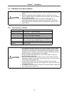
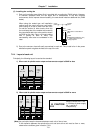
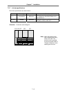
7-2-7 Link bar specifications
The link bar specifications are shown below.
Wire usage Terminal block Details
L+, L–
Not possible
M6 screw
Connection wire for supplying the converter
DC voltage from the power supply unit to
each drive unit.
L1+, L1–
Possible
M4 screw
Connection wire for supplying control power
200VAC to 230V to each unit.
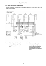
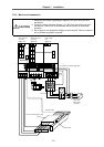
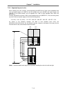
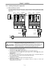
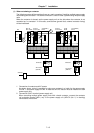
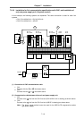
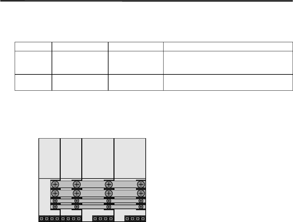
<Remarks> Connection outline diagram
L+
L–
L1+
L1–
A-SP
B-SP
A-V1/V2
B-V1/V2
B-V14/V24
B-V14L
A-CV
B-CV
Note) Mount the terminal cover
after completing the wiring
shown on the left. The
terminal cover is provided
for each unit width. Refer to
"Chapter 3 Selection" when
selecting the wire size.