


121
PARAMETERS
5
Setting of acceleration/deceleration time and acceleration/ deceleration pattern
5.8.4 Shortest acceleration/deceleration (automatic acceleration/deceleration)
(Pr. 61 to Pr. 63, Pr. 292, Pr. 293)
The above parameters can be set when Pr. 160 User group read selection ="0". (Refer to page 167)
(1) Shortest acceleration/deceleration mode (Pr. 292 = "1, 11", Pr. 293)
Set when you want to accelerate/decelerate the motor for the shortest time. It is desired to make acceleration/deceleration
in a shorter time for a machine tool etc. but the design values of machine constants are unknown.
Acceleration/deceleration speed is automatically adjusted at a start of acceleration/deceleration from the value of the
setting value of Pr. 7 Acceleration time and Pr. 8 Deceleration time so that acceleration/deceleration is made with the
maximum torque the inverter can output. (The setting values of Pr. 7 and Pr. 8 are not changed.)
Either acceleration or deceleration can be made in the shortest time using Pr. 293 Acceleration/deceleration separate
selection. When the setting value is "0" (initial value), both acceleration and deceleration can be made in the shortest time.
Set "11" when an optional MRS type, MYS type brake resistor, high-duty brake resistor or brake unit is connected.
Deceleration time can be further shortened.
When the shortest/acceleration mode is selected, the stall prevention operation level during acceleration/deceleration from
the value of becomes 150% (adjustable using Pr. 61 to Pr. 63 ). Setting of Pr. 22 Stall prevention operation level is used only
during a constant speed operation.
It is inappropriate to use for the following applications.
a) Machine with a large inertia such as a fan (more than 10 times). Since stall prevention operation will be activated for
a long time, this type of machine may trip due to motor overloading, etc.
b) To perform operation with a constant acceleration/deceleration time.
The inverter operates in the same conditions as when appropriate values are set in each parameter even if
acceleration/deceleration time and V/F pattern are not set. This function is useful when you just want to operate, etc.
without fine parameter setting.
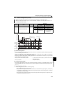
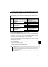
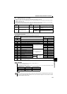
Parameter
Number
Name
Initial
Value
Setting
Range
Description
61 Reference current
9999
0 to 500A
Set the reference current during shortest
acceleration/deceleration.
9999 Rated inverter output current value is reference
62
Reference value at
acceleration
9999
0 to 200% Set the limit value during shortest acceleration.
9999 150% is a limit value
63
Reference value at
deceleration
9999
0 to 200% Set the limit value during shortest deceleration.
9999 150% is a limit value
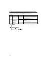
292
Automatic acceleration/
deceleration
0
0 Normal mode
1 Shortest acceleration/deceleration (without brake)
11 Shortest acceleration/deceleration (with brake)
7, 8 For manufacturer setting. Do not set.
293
Acceleration/deceleration
separate selection
0
0
Both acceleration and deceleration are made in the
shortest acceleration/deceleration mode
1
Only acceleration is made in the shortest
acceleration/deceleration mode
2
Only deceleration is made in the shortest
acceleration/deceleration mode
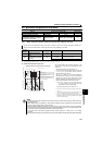
REMARKS
Even if automatic acceleration/deceleration mode has been selected, inputting the RT signal (second function selection) during
an inverter stop will switch to the normal operation and give priority to the second function selection. Note that RT signal input is
invalid even if RT signal is input during operation in the automatic acceleration/deceleration mode.
Since acceleration/deceleration is made with the stall prevention operation being activated, the acceleration/deceleration speed
always varies according to the load conditions.
Note that when proper values are set in Pr. 7 and Pr. 8, acceleration/deceleration time may be shorter than selecting shortest
acceleration/deceleration mode.