


173
PARAMETERS
5
Special operation and frequency control
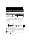
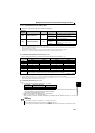
5.18.2 Droop control (Pr. 286, Pr. 287)
This function is designed to balance the load in proportion to the load torque to provide the speed drooping
characteristic under Advanced magnetic flux vector control.
This function is effective for balancing the load when using multiple inverters.
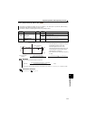
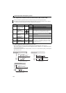
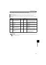
Parameter
Number
Name
Initial
Value
Setting
Range
Description
286 Droop gain
0%
0 Droop control is invalid (Normal operation)
0.1% to
100%
Droop control is valid
Drooping amount at the rated torque as a percentage with
respect to the rated motor frequency.
287
Droop filter time
constant
0.3s 0 to 1s Time constant of the filter applied on the torque current.
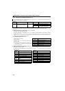
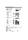
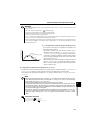
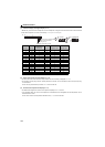
(1) Droop control
The output frequency is changed according to
the magnitude of torque current under
Advanced magnetic flux vector control.
The drooping amount at the rated torque is set
by the droop gain as a percentage using the
rated frequency as a reference.
The maximum droop compensation frequency
is 120Hz.
Droop compensation
frequency
=
Torque current after filtering
×
Pr. 84 Rated motor frequency × Pr. 286 Droop gain
Rated value of torque current 100
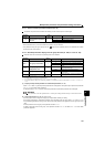
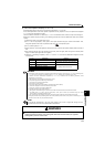
REMARKS
Set the droop gain to about the rated slip of the motor.
The maximum value of frequency after droop compensation is either 120Hz or Pr. 1 Maximum frequency, whichever is smaller.
Parameters referred to
Pr. 1 Maximum frequency Refer to page 105
AD
MFVC
AD
MFVC
AD
MFVC
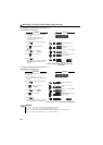
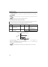
Droop compensation
frequency
Torque
100%
Droop
gain
-100%
Frequency command
0
Rated frequency
Rated slip =
Synchronous speed at base frequency - rated speed
× 100[%]
Synchronous speed at base frequency