


177
PARAMETERS
5
Useful functions
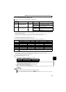
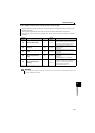
5.19.2 Display of the life of the inverter parts (Pr. 255 to Pr. 259)
Degrees of deterioration of main circuit capacitor, control circuit capacitor, cooling fan and inrush current limit circuit can
be diagnosed by monitor.
When any part has approached the end of its life, an alarm can be output by self diagnosis to prevent a fault.
(Use the life check of this function as a guideline since the life except the main circuit capacitor is calculated
theoretically.)
Parameter
Number
Name Initial Value
Setting
Range
Description
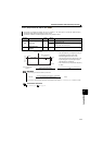
255 Life alarm status display
0 (0 to 15)
Displays whether the control circuit capacitor,
main circuit capacitor, cooling fan, and each parts
of the inrush current limit circuit has reached the
life alarm output level or not. (Reading only)
256
Inrush current limit circuit
life display
100% (0 to 100%)
Displays the deterioration degree of the inrush
current limit circuit.
(Reading only)
257
Control circuit capacitor life
display
100% (0 to 100%)
Displays the deterioration degree of the control
circuit capacitor.
(Reading only)
258
Main circuit capacitor life
display
100% (0 to 100%)
Displays the deterioration degree of the main
circuit capacitor.
(Reading only)
The value measured by Pr. 259 is displayed.
259
Main circuit capacitor life
measuring
0
0, 1
(2, 3, 8, 9)
Setting "1" and turning the power supply off starts
the measurement of the main circuit capacitor life.
When the Pr. 259 value is "3" after powering on
again, the measuring is completed.
Writes deterioration degree in Pr. 258.
The above parameters can be set when Pr. 160 User group read selection = "0". (Refer to page 167)
REMARKS
Since repeated inrush currents at power ON will shorten the life of the converter circuit, frequent starts and stops of the
magnetic contactor must be avoided.