


14
Wiring
2.1 Wiring
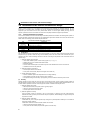
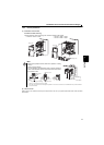
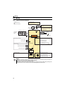
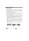
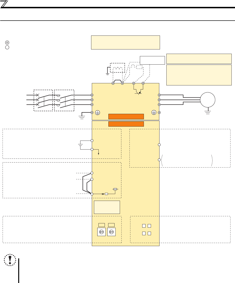
2.1.1 Terminal connection diagram
NOTE
To prevent a malfunction caused by noise, separate the signal cables more than 10cm from the power cables. Also
separate the main circuit wire of the input side and the output side.
After wiring, wire offcuts must not be left in the inverter.
Wire offcuts can cause an alarm, failure or malfunction. Always keep the inverter clean. When drilling mounting holes
in an enclosure etc., take care not to allow chips and other foreign matter to enter the inverter.
Inrush current
limit circuit
Output
shutoff
circuit
Earth
(Ground)
Motor
IM
Earth (Ground)
Three-phase
AC power
supply
MCCB MC
R/L1
P1 P/+
PR
N/-
S/L2
T/L3
U
V
W
Earth
(Ground)
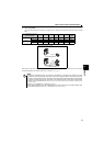
*3 Brake resistor (FR-ABR, MRS, MYS type)
Install a thermal relay to prevent an
overheat and burnout of the brake resistor.
(The brake resistor cannot be connected
to the 0.1K and 0.2K.)
*2 A brake transistor is not built-in to the 0.1K
and 0.2K.
*1. DC reactor (FR-HEL)
When connecting a DC reactor, remove the
jumper across P1 and P/+.
Control circuit terminal
Main circuit terminal
Sink logic
Jumper
*1
*3
*2
Main circuit
Control circuit
R
Brake unit
(Option)
24V external power supply
SD
+24
Open collector output Y0
(Safety monitor output 2)
Open collector output
Open collector output common
Sink/source common
Y0
SE
FL remote
communication
connector
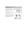
Node address setting
0
9
8
7
6
5
4
3
2
1
0
9
8
7
6
5
4
3
2
1
X1
X10
D1 D2
D3 D4
LED (operation status display)
D1:
Communication setting status LED (CHG)
D2: Device status LED (DEV)
D3: Reception/transmission LED (TX/RX)
D4: Remote status LED (RMT)
Safety stop signal
S1
S2
PC
Safety stop input (Channel 1)
Shorting
wire
Safety stop input common
Safety stop input (Channel 2)
24V power supply
Common terminal
24V