


196
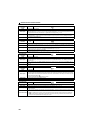
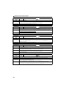
Causes and corrective actions
Operation panel
indication
RB
Name
Regenerative brake prealarm
Description
Appears if the regenerative brake duty reaches or exceeds 85% of the Pr. 70 Special regenerative brake duty value.
When the setting of Pr. 70 Special regenerative brake duty is the initial value (Pr. 70 = "0"), this warning does not occur. If
the regenerative brake duty reaches 100%, a regenerative overvoltage (E. OV_) occurs.
Check point
Check that the brake resistor duty is not high.
Check that the Pr. 30 Regenerative function selection and Pr. 70 Special regenerative brake duty settings are correct.
Corrective action
Increase the deceleration time.
Check that the Pr. 30 Regenerative function selection and Pr. 70 Special regenerative brake duty settings.
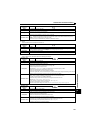
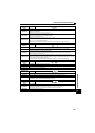
Operation panel
indication
TH
Name
Electronic thermal relay function prealarm
Description
Appears if the cumulative value of the Pr. 9 Electronic thermal O/L relay reaches or exceeds 85% of the preset level. If
it reaches 100% of the Pr. 9 Electronic thermal O/L relay setting, a motor overload trip (E. THM) occurs.
Check point
Check for large load or sudden acceleration.
Is the Pr. 9 Electronic thermal O/L relay setting is appropriate? (Refer to page 123)
Corrective action
Reduce the load and frequency of operation.
Set an appropriate value in Pr. 9 Electronic thermal O/L relay. (Refer to page 123)
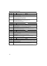
Operation panel
indication
MT
Name
Maintenance signal output
Description
Indicates that the cumulative energization time of the inverter has reached a given time.
When the setting of Pr. 504 Maintenance timer alarm output set time is the initial value (Pr. 504 = "9999"), this warning
does not occur.
Check point
The Pr. 503 Maintenance timer setting is larger than the Pr. 504 Maintenance timer alarm output set time setting. (Refer to
page 180).
Corrective action
Setting "0" in Pr. 503 Maintenance timer erases the signal.
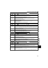
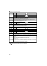
Operation panel
indication
UV
Name
Undervoltage
Description
If the power supply voltage of the inverter decreases, the control circuit will not perform normal functions. In addition,
the motor torque will be insufficient and/or heat generation will increase. To prevent this, if the power supply voltage
decreases below about 115VAC (about 230VAC for 400V class, about 58VAC for 100V class), this function stops the
inverter output and displays .
An alarm is reset when the voltage returns to normal.
Check point Check that the power supply voltage is normal.
Corrective action Check the power supply system equipment such as power supply.
Operation panel
indication
SA
Name
Safety stop
Description Appears when safety stop function is activated (during output shutoff). (Refer to page 24)
Check point
If the indication appears when safety stop function is not used, check that shorting wires between S1 and PC, S2 and
PC are connected.
Corrective action
When not using the safety stop function, short across terminals S1 and PC and across S2 and PC with shorting
wire for the inverter to run.
If is indicated when across S1 and PC and across S2 and PC are both shorted while using the safety stop
function (drive enabled), internal failure might be the cause. Check the wiring of terminals S1, S2 and PC and
contact your sales representative if the wiring has no fault.