


197
Causes and corrective actions
6
TROUBLESHOOTING
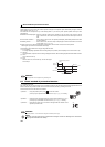
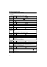
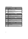
(3) Alarm
When an alarm occurs, the output is not shut off.
(4) Fault
When a fault occurs, the inverter trips and a fault signal is output.
Operation panel
indication
EV
Name
24V external power supply operation
Description
Flickers when the main circuit power supply is OFF and the 24V external power is being supplied.
Check point
Check if the 24V external power is supplied.
Check if the (main circuit) power supply for the inverter is ON. Check if the voltage is low.
Check if the jumper between terminal P/+ and P1 is removed.
Corrective action
Turn ON the power supply for the inverter (main circuit).
If appears by turning ON the power supply of the inverter (main circuit) while the external 24V power is
supplied, check the power supply (for the main circuit).
Check if the jumper is installed securely between the terminal P/+ and P1.
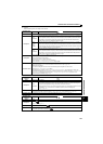
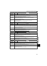
Operation panel
indication
FN
Name
Fan alarm
Description
For the inverter that contains a cooling fan, appears on the operation panel when the cooling fan stops due to
an alarm or different operation from the setting of Pr. 244 Cooling fan operation selection.
Check point
Check the cooling fan for an alarm.
Corrective action
Check for fan alarm. Please contact your sales representative.
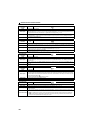
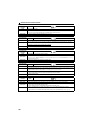
Operation panel
indication
E.OC1
Name
Overcurrent trip during acceleration
Description
When the inverter output current reaches or exceeds approximately 230% of the rated current during acceleration, the
protective circuit is activated and the inverter trips.
Check point
Check for sudden acceleration.
Check that the downward acceleration time is not long for lifts.
Check for output short-circuit/ground fault.
Check that the Pr. 3 Base frequency setting is not 60Hz when the motor rated frequency is 50Hz.
Check if the stall prevention operation level is set too high.
Check if the fast-response current limit operation is disabled.
Check that regeneration is not performed frequently. (Check that the output voltage becomes larger than the V/F
reference value at regeneration and overcurrent occurs due to the high voltage.)
Corrective action
Increase the acceleration time. (Shorten the downward acceleration time for lifts.)
When "E.OC1" is always lit at starting, disconnect the motor once and start the inverter.
If "E.OC1" is still lit, contact your sales representative.
Check the wiring to make sure that output short circuit/ground fault does not occur.
Set 50Hz in Pr. 3 Base frequency. (Refer to page 107)
Lower the setting of stall prevention operation level. (Refer to page 101).
Activate the fast-response current limit operation.
Set base voltage (rated voltage of the motor, etc.) in Pr. 19 Base frequency voltage. (Refer to page 107)
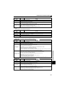
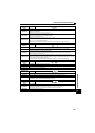
Operation panel
indication
E.OC2
Name
Overcurrent trip during constant speed
Description
When the inverter output current reaches or exceeds approximately 230% of the rated current during constant speed
operation, the protective circuit is activated and the inverter trips.
Check point
Check for sudden load change.
Check for output short-circuit/ground fault.
Check if the stall prevention operation level is set too high.
Check if the fast-response current limit operation is disabled.
Corrective action
Keep load stable.
Check the wiring to make sure that output short circuit/ground fault does not occur.
Lower the setting of stall prevention operation level. (Refer to page 101).
Activate the fast-response current limit operation.