


60
Cyclic transmission
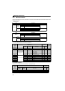
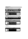
(3) Life/alarm
Whether the control circuit capacitor, main circuit capacitor, cooling fan, and each parts of the inrush current limit circuit have
reached the life alarm output level or not can be checked.
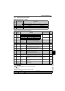
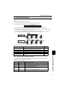
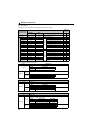
(4) Output frequency monitor
The output frequency of the inverter can be monitored in 0.01Hz increments.
Example:
If the monitor value is 120.00Hz, 12000 (the value multiplied by 100) is displayed.
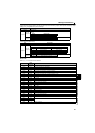
(5) Output current monitor
The output current of the inverter can be monitored in 0.1A increments.
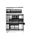
Bit Name Description
8 Control circuit capacitor life
0: without alarm, 1: with alarm
The control circuit capacitor life is calculated from the energization time and temperature
according to the operating status, and is counted down from 100%.
An alarm is output when the control circuit capacitor life falls below 10%.
(The setting value goes back to 0 when the part is replaced.)
9 Main circuit capacitor life
0: without alarm, 1: with alarm
On the assumption that the main circuit capacitor capacitance at factory shipment is 100%, the
capacitor life is checked every time measurement is made. An alarm is output when the measured
value falls below 85%. The life check of the main circuit capacitor can be performed by measuring
at the maintenance time, etc.
After setting "1" in Pr. 259 Main circuit capacitor life measuring, switch OFF power once, then ON
again to check that Pr. 259 = "3" (measuring completion).
(The setting value goes back to 0 when the part is replaced.)
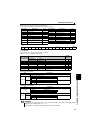
10 Cooling fan life
0: without alarm, 1: with alarm
This function detects that the cooling fan speed falls 50% or below and outputs an alarm.
(The setting value goes back to 0 when the part is replaced.)
11 Inrush current limit circuit life
0: without alarm, 1: with alarm
Counts the number of contact (relay, contactor, thyristor) ON times and counts down every 100%
(0 times) to 1%/10,000 times.
Outputs an alarm when the speed reaches 10% (900000 times).
(The setting value goes back to 0 when the part is replaced.)
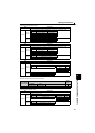
12
FIN signal
(Heatsink overheat pre-alarm)
0: without alarm, 1: with alarm
Output when the heatsink temperature reaches about 85% of the heatsink overheat protection
providing temperature. (Refer to page 199 for the details.)
13 Alarms 0: without display, 1: with display
14 — (not used) (Always 0)
15
Y95 signal
(maintenance timer)
0: normal, 1: maintenance timer has elapsed
When the Pr. 503 Maintenance timer setting has elapsed the time (100h increments) set in Pr.504
Maintenance timer alarm output set time, the value changes to 1. (Turn ON Y95 signal.)
When Pr. 504 = "9999", no function is selected. (Refer to page 180 for the details.)
REMARKS
y The values of each bit, "0" and "1," indicate "OFF" and "ON."
Bit Range Unit
0 to 15 0.00Hz to 400.00Hz 0.01Hz
REMARKS
y Regardless of the Pr.37 setting, the value is always displayed in frequency (Hz).
Bit Range Unit
0 to 15 0.0A to 3276.7A 0.1A