


219
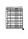
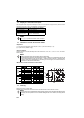
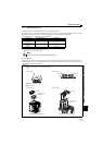
Measurement of main circuit voltages, currents and powers
7
PRECAUTIONS FOR MAINTENANCE AND INSPECTION
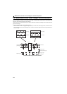
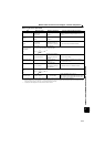
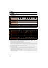
Measuring Points and Instruments
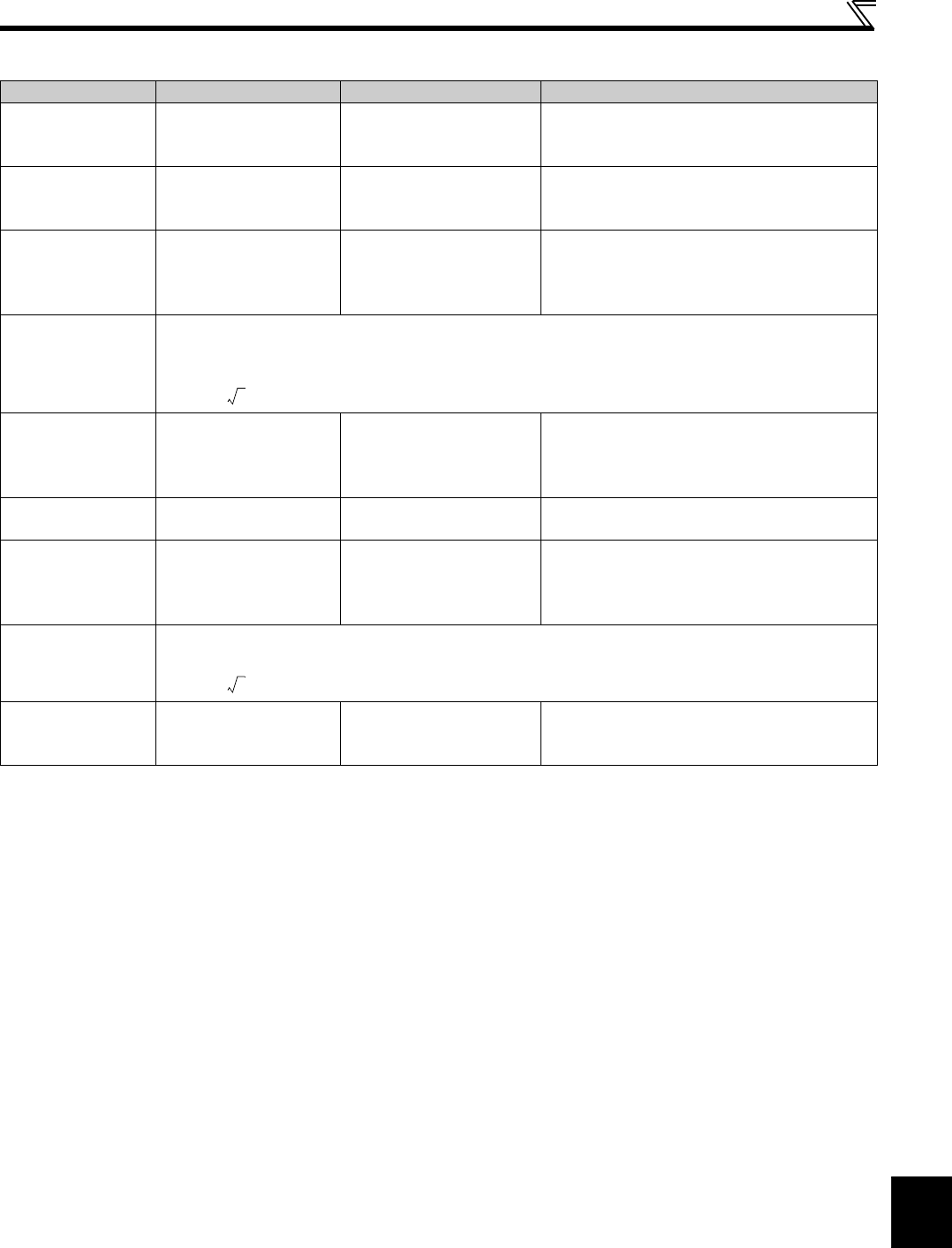
Item Measuring Point Measuring Instrument Remarks (Reference Measured Value)
Power supply voltage
V
1
Across R/L1 and S/L2
S/L2 and T/L3
T/L3 and R/L1
Moving-iron type AC
voltmeter ∗3
Commercial power supply
Within permissible AC voltage fluctuation (Refer to
page 224)
Power supply side
current
I
1
R/L1, S/L2, T/L3 line
current
Moving-iron type AC
ammeter ∗3
Power supply side
power
P
1
R/L1, S/L2, T/L3 and
R/L1 and S/L2,
S/L2 and T/L3,
T/L3 and R/L1
Digital power meter
(designed for inverter) or
electrodynamic type single-
phase wattmeter
P
1=W11+W12+W13 (3-wattmeter method)
Power supply side
power factor
Pf
1
Calculate after measuring power supply voltage, power
supply side current and power supply side power.
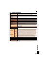
Output side voltage
V
2
Across U and V,
V and W and W and U
Rectifier type AC voltage
meter ∗1 ∗3
(moving-iron type cannot
measure)
Difference between the phases is within 1% of the
maximum output voltage.
Output side current
I
2
U, V and W line currents
Moving-iron type AC
ammeter ∗2 ∗3
Difference between the phases is 10% or lower of
the rated inverter current.
Output side power
P
2
U, V, W and
U and V, V and W
Digital power meter
(designed for inverter) or
electrodynamic type single-
phase wattmeter
P
2 = W21 + W22
2-wattmeter method (or 3-wattmeter method)
Output side power
factor
Pf
2
Calculate in similar manner to power supply side power factor.
Converter output Across P/+ and N/-
Moving-coil type
(such as tester)
Inverter LED display is lit. 1.35 × V1
380V maximum during regeneration for 200V class
760V maximum during regeneration for 400V class
∗1 Use an FFT to measure the output voltage accurately. An FA tester or general measuring instrument cannot measure accurately.
∗2 When the carrier frequency exceeds 5kHz, do not use this instrument since using it may increase eddy-current losses produced in metal parts inside the
instrument, leading to burnout. In this case, use an approximate-effective value type.
∗3 A digital power meter (designed for inverter) can also be used to measure.
Pf1
P1
3V1 I× 1
------------------------
100×=
%
Pf2
P2
3V2 I2×
------------------------
100×=
%