


178
Useful functions
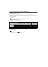
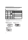
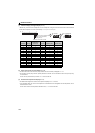
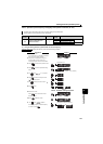
(1) Life alarm display and signal output (Pr. 255)
Whether any of the control circuit capacitor, main circuit capacitor, cooling fan and inrush current limit circuit has reached
the life alarm output level or not can be checked by Pr. 255 Life alarm status display.
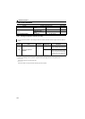
(2) Inrush current limit circuit life display (Pr. 256)
The life of the inrush current limit circuit (relay, contactor and inrush resistor) is displayed in Pr. 256 .
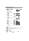
The number of contact (relay, contactor, thyristor) ON times is counted, and it is counted down from 100% (0 times) every
1%/10,000 times.
As soon as 10% (900,000 times) is reached, Pr. 255 bit 3 is turned ON.
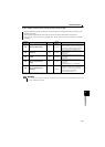
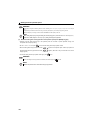
(3) Control circuit capacitor life display (Pr. 257)
The deterioration degree of the control circuit capacitor is displayed in Pr. 257 as a life.
In the operating status, the control circuit capacitor life is calculated from the energization time and temperature, and is
counted down from 100%.
As soon as the control circuit capacitor life falls below 10%, Pr. 255 bit 0 is turned ON.
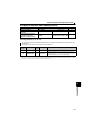
Pr. 255
(decimal)
Bit
(binary)
Inrush Current
Suppression
Circuit Life
Cooling
Fan Life
Main Circuit
Capacitor Life
Control Circuit
Capacitor Life
15 1111
14 1110
×
13 1101
×
12 1100
××
11 1011
×
10 1010 × ×
9 1001
××
8 1000
×× ×
7 0111 ×
60110 ×
×
5 0101 ×
×
4 0100 × ××
3 0011 ××
2 0010 ××
×
1 0001 ×××
0 0000 ××× ×
: With warnings, ×: Without warnings
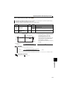
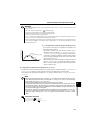
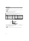
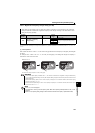
000000000000100
bit0 Control circuit capacitor life
1
15bit 7 0
bit1 Main circuit capacitor life
bit2 Cooling fan life
bit3 Inrush current limit circuit life
Pr. 255 read Pr. 255 setting read
Bit image is displayed
in decimal