


225
Common specifications
8
SPECIFICATIONS
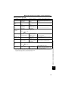
8.2 Common specifications
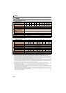
Control specifications
Control method
Soft-PWM control/high carrier frequency PWM control (V/F control, Advanced magnetic flux vector control,
General-purpose magnetic flux vector control, Optimum excitation control are available)
Output frequency range 0.2 to 400Hz
Frequency setting resolution
(Digital input)
0.01Hz
Frequency accuracy
(Digital input)
Within 0.01% of the set output frequency
Voltage/frequency characteristics Base frequency can be set from 0 to 400Hz, Constant-torque/variable torque pattern can be selected
Starting torque 200% or more (at 0.5Hz)...when Advanced magnetic flux vector control is set (3.7K or lower)
Torque boost
Manual torque boost
Acceleration/deceleration time setting
0.01 to 360s, 0.1 to 3600s (acceleration and deceleration can be set individually), linear or S-pattern acceleration/
deceleration modes are available.
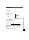
DC injection brake
Operation frequency (0 to 120Hz), operation time (0 to 10s), operation voltage (0 to 30%) can be changed.
Stall prevention operation level Operation current level can be set (0 to 200% adjustable), whether to use the function or not can be selected.
Operation specifications
Frequency setting signal
(Digital input)
Signals are entered from the operation panel or through FL remote communication. Frequency setting increments
can be set.
Start signal Forward and reverse rotation can be selected.
Operational functions
Maximum/minimum frequency setting, frequency jump operation, automatic restart after instantaneous power
failure operation, forward/reverse rotation prevention, remote setting, second function, multi-speed operation,
stop-on contact control, droop control, regeneration avoidance, slip compensation, operation mode selection,
offline auto tuning function
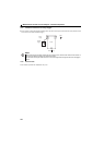
Safety stop function∗2
Safety shutoff signal can be input from terminals S1 and S2. (compliant with EN ISO 13849-1 Category 3 / PLd
EN62061 / IEC61508 SIL2)
Output signal
Open collector output (One terminal)
Safety monitor output 2 (Fixed)
Operating status
Indication on the
operation panel
Operating status
The following operating status can be displayed: output frequency, motor current (steady), output voltage,
frequency setting, cumulative energization time, actual operation time, motor torque, converter output voltage,
regenerative brake duty, electronic thermal relay function load factor, output current peak value, converter output
voltage peak value, motor load factor, inverter output terminal monitor, output power, cumulative power, motor
thermal load factor, and inverter thermal load factor.
Fault record
Fault record is displayed when a fault occurs. Past 8 fault records (output voltage/current/frequency/cumulative
energization time right before the fault occurs) are stored.
Protective/warning
function
Protective
functions
Overcurrent during acceleration, overcurrent during constant speed, overcurrent during deceleration, overvoltage
during acceleration, overvoltage during constant speed, overvoltage during deceleration, inverter protection
thermal operation, motor protection thermal operation, heatsink overheat, input phase failure, stall prevention
stop, output side earth (ground) fault overcurrent at start∗4, output short circuit, output phase failure, option fault,
parameter error, retry count excess ∗4, CPU fault, brake transistor alarm, inrush resistance overheat,
communication error, safety circuit fault
Warning
functions
Fan alarm∗2, overcurrent stall prevention, overvoltage stall prevention, PU stop, parameter write error,
regenerative brake prealarm ∗4, electronic thermal relay function prealarm, maintenance output ∗4, undervoltage,
operation panel lock, password locked∗4, inverter reset, safety stop, 24V external power supply operation
Environment
Surrounding air temperature -10°C to +50°C (non-freezing) ∗3
Ambient humidity 90%RH or less (non-condensing)
Storage temperature∗1
-20°C to +65°C
Atmosphere
Indoors (without corrosive gas, flammable gas, oil mist, dust and dirt etc.)
Altitude/vibration
Maximum 1000m above sea level, 5.9m/s
2
or less at 10 to 55Hz (directions of X, Y, Z axes)
∗1 Temperatures applicable for a short time, e.g. in transit.
∗2 As the FR-E720-0.1KNF to 0.75KNF, FR-E740-0.4KNF and 0.75KNF
are not provided with the cooling fan, this alarm is not available.
∗3 When using the inverters at the surrounding air temperature of 40°C or less, the inverters can be installed closely attached (0cm clearance).
∗4 This protective function is not available in the initial status.